Category Archives: Projects

DEF CON 29 Mask

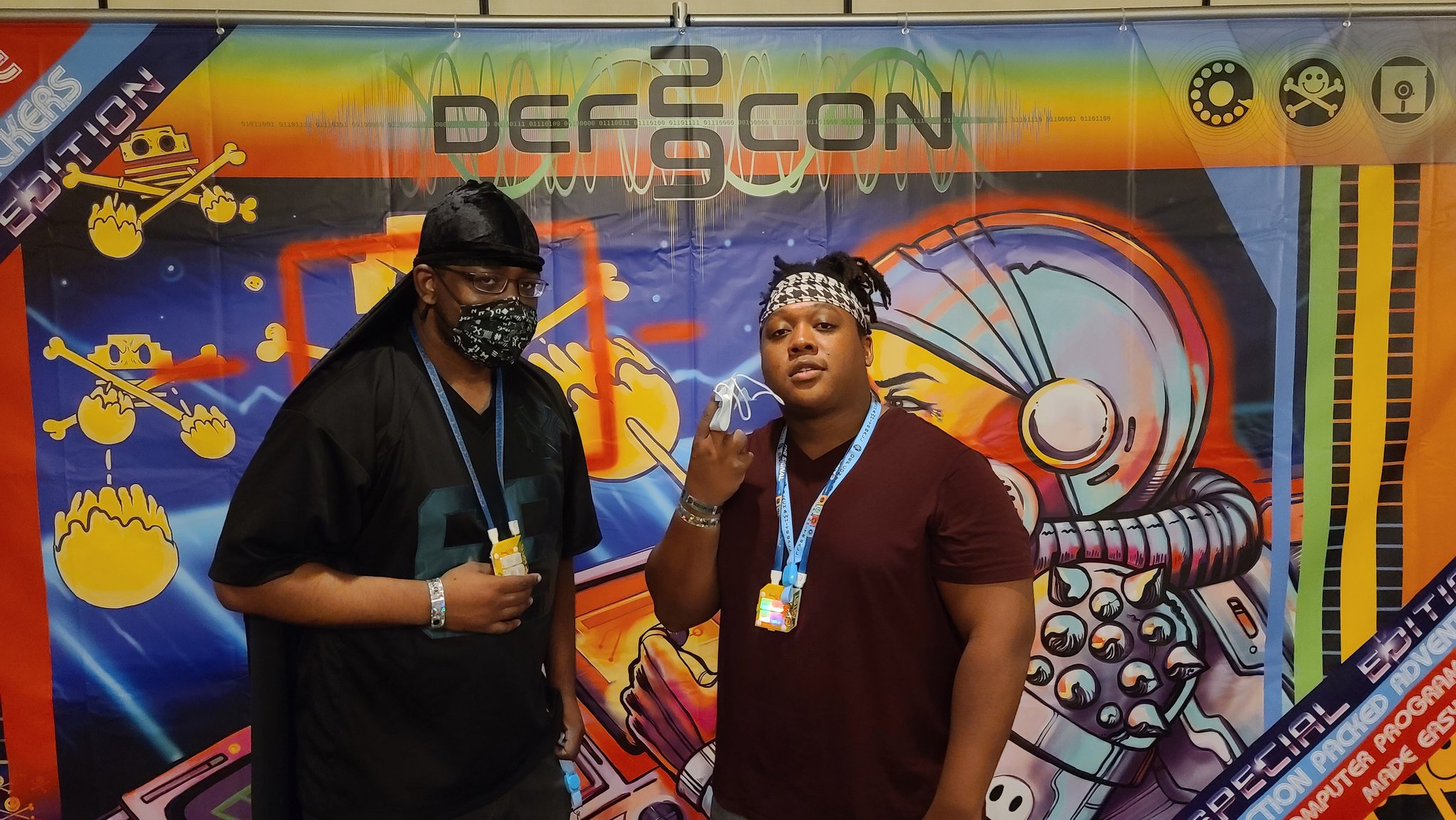
DEF CON 29 happened in Las Vegas, NV from August 5 to August 8, 2021. DC28 was entirely virtual. This year, the conference operated in a hybrid model, and in-person attendees were required to demonstrate proof of vaccination and to mask whenever in conference spaces. This strategy was enormously successful, and DC29 did not function as a COVID super-spreader event. I attended, and because I was going to mask the entire time, I decided to lean into it.

Photo by Andrea Peterson. Source: Fear and Covid in Las Vegas: Pen testing Hacker Summer Camp’s mask policies

I started with a 3M 6503QL “Rugged Comfort” respirator, a pair of 3M 6001 filter cartridges, 501 translucent filter retainers, and P95 filters. This respirator is pretty comfortable, supported by a head strap and pulled snug by a neck strap. It has a quick-release mechanism that removes tension on the head strap and lets it hang loosely below my face. Most importantly, those filter cartridges provide plenty of room for components.

How it started

I wanted this mask to do something, and just covering it in der blinkenlights was not enough. I thought about making it wifi reactive (visualizing observed deauths, for example), or offering an open web service that people nearby could use to modify the behavior of the lights. In the end, I decided that it would be really cool if it could visualize its core function by changing the color of the lights as I breathe in and out.

Adafruit BME680 atmospheric sensor breakout. I only use the atmospheric pressure.

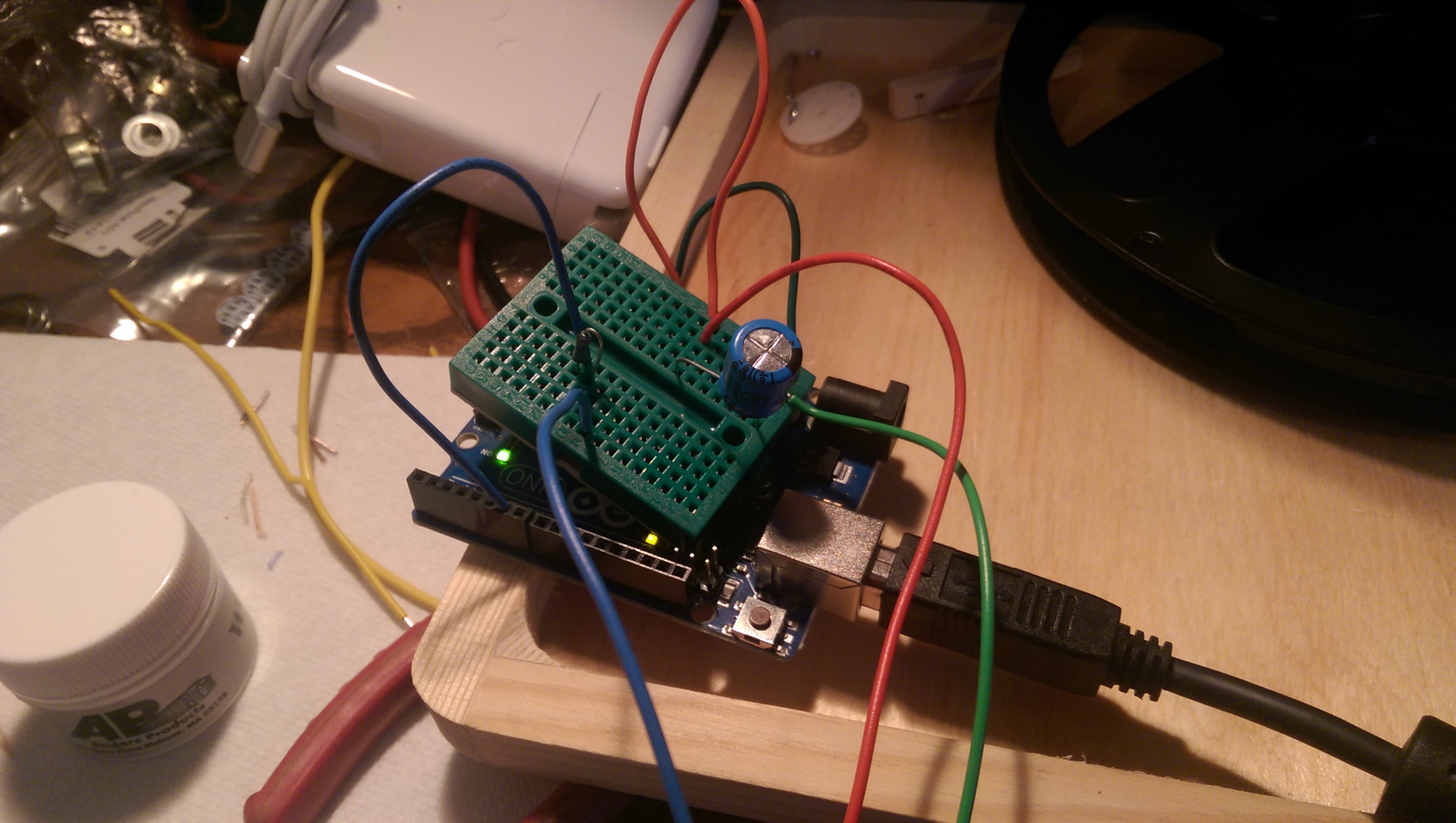
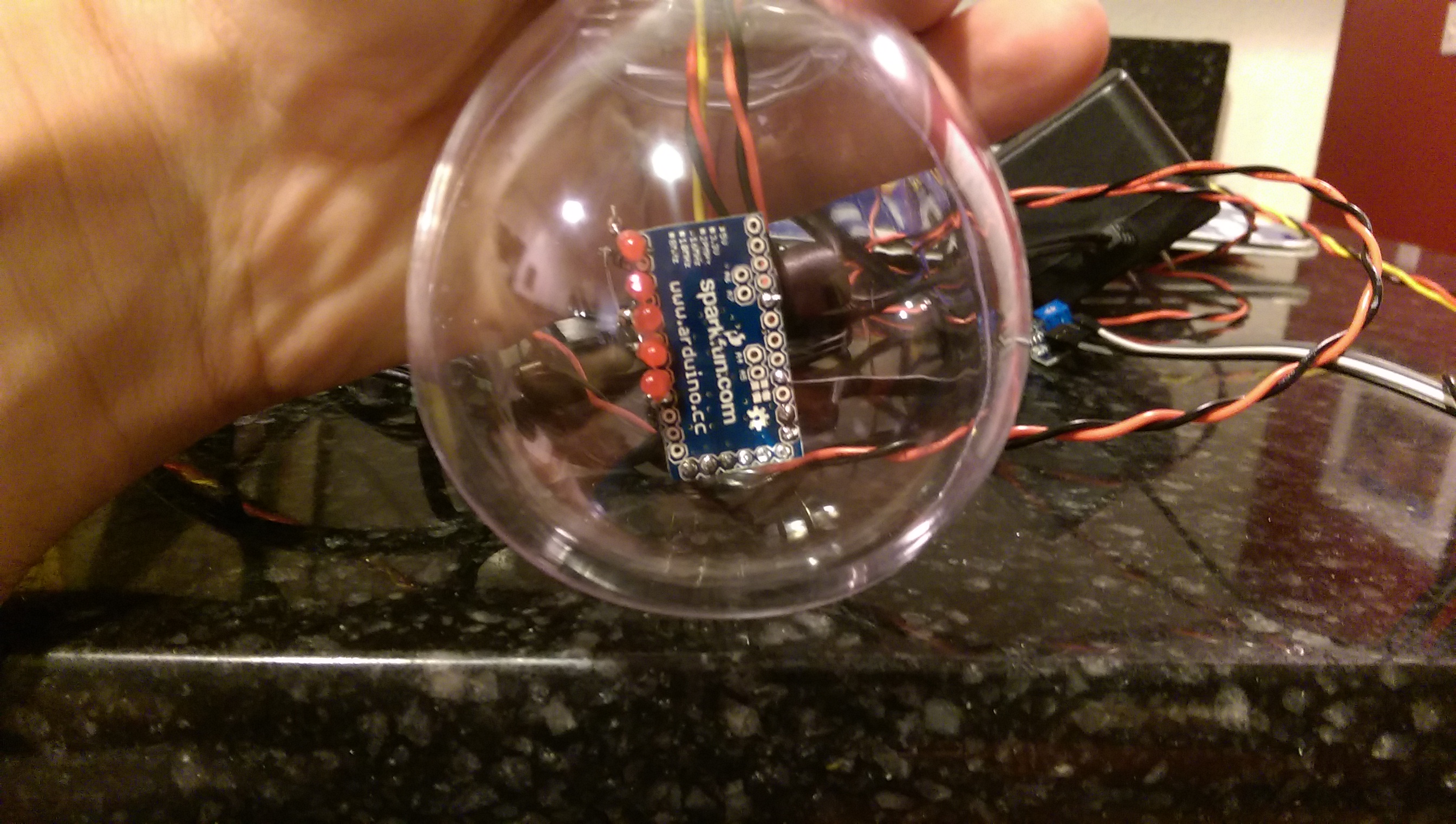
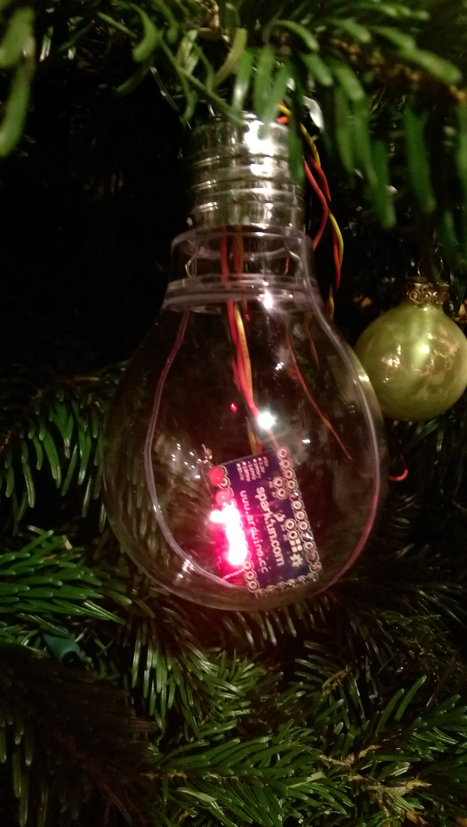
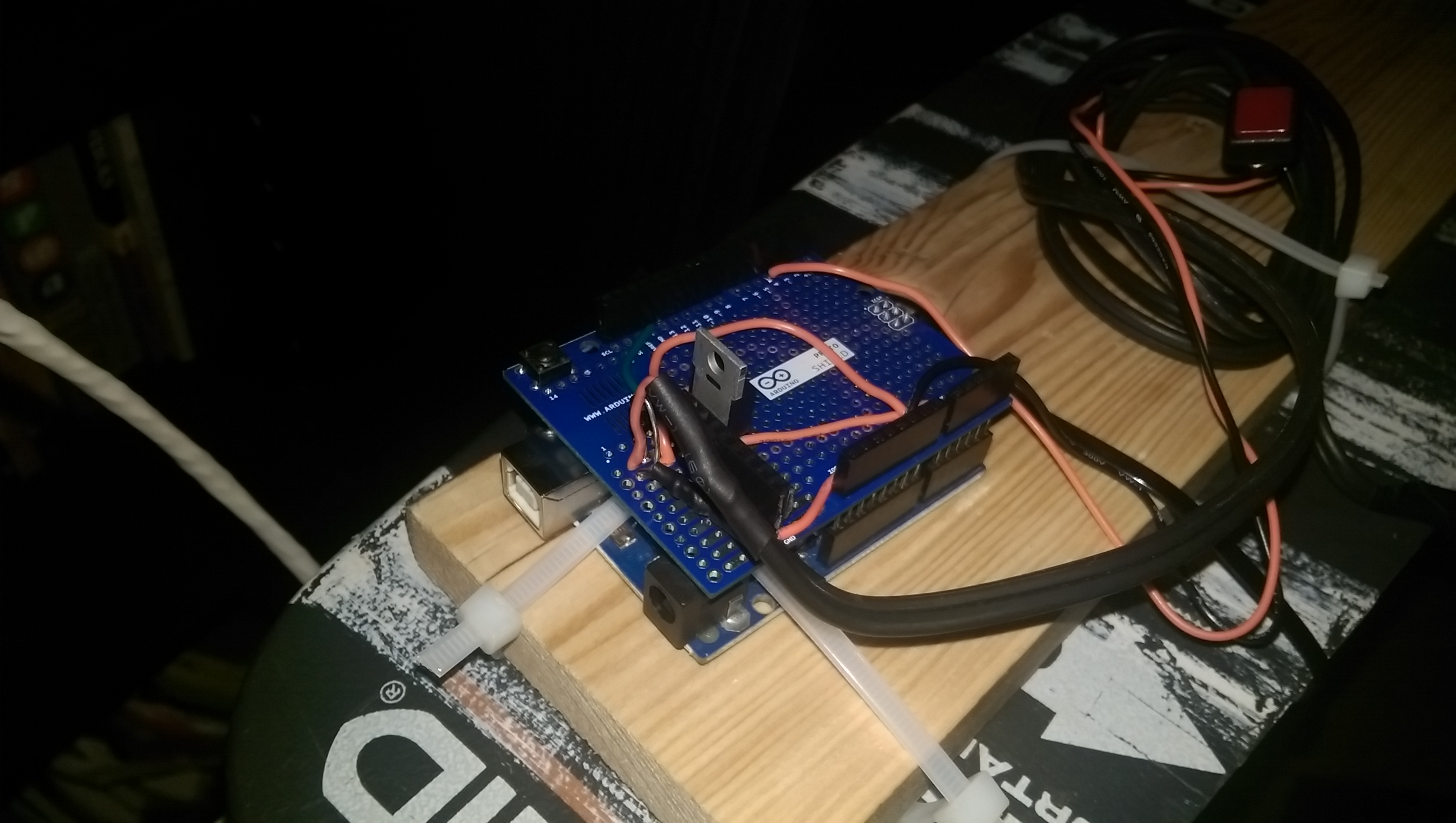
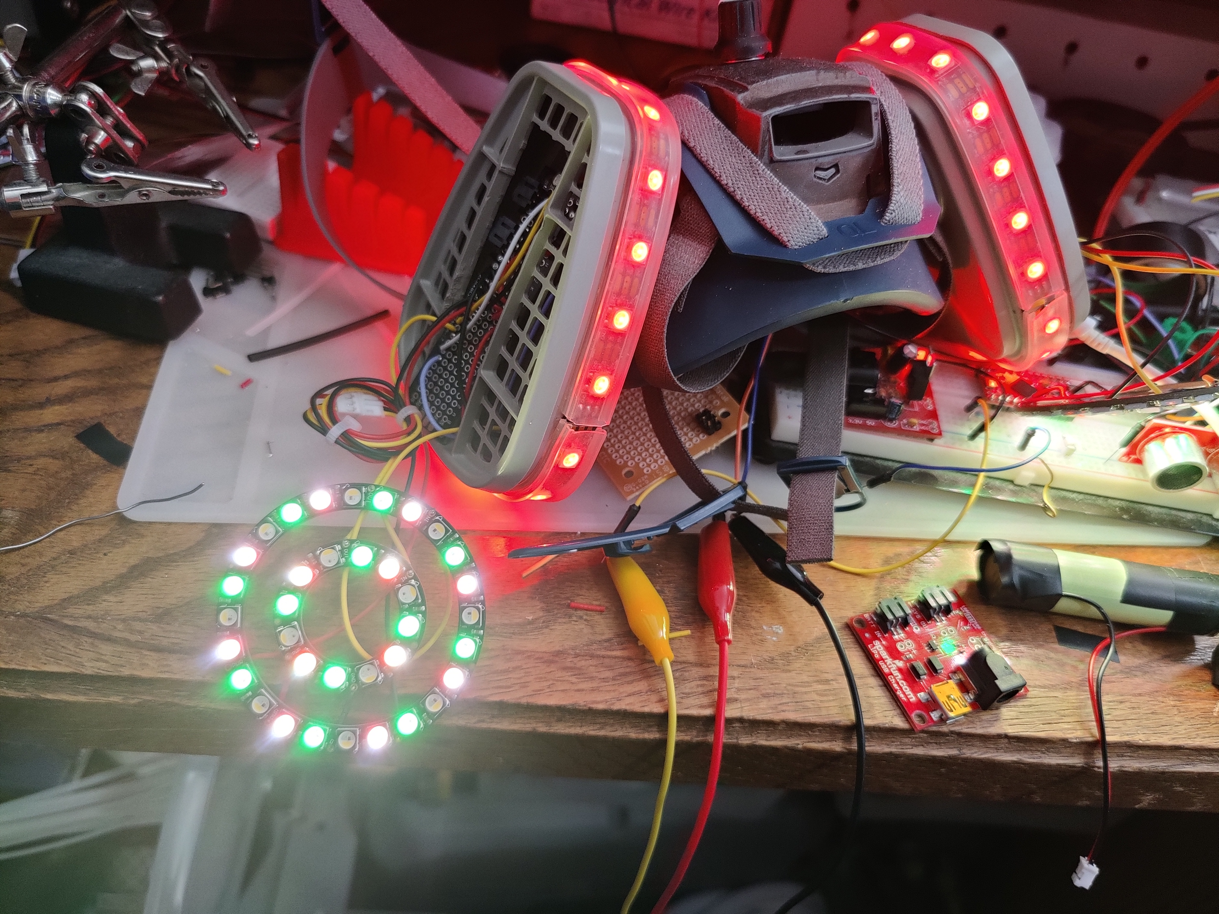
To detect breathing, I used the atmospheric pressure sensor from a Bosch BME680 atmospheric sensor (in an Adafruit breakout board). I needed this mask to be an actual safety device suitable for protecting myself and those around me, so I removed all of the valves and plugged the unfiltered output hole (after several attempts, I went with carved pencil eraser). This created enough of a pressure differential inside the masklow pressure when I breathe in, high pressure when I breathe out—that I could detect it with the sensor and use it to inform the behavior of the lights. Here’s an early test of the concept: the lights turn green when the pressure drops below a threshold and red when the pressure rises above a threshold.

To start, I hollowed out the filter cartridges. Each cartridge has a hole on one side where it links up with the mask, a thin filter layer, densely packed charcoal, another filter layer, and then a thick plastic mesh. On top of this would go one more P95 filter and a translucent retainer. I clipped away a big piece of the plastic mesh and emptied the charcoal. I also wound up cutting away some supporting structure inside the cartridge and in the hole that passes through to the mask. This gave me space to fit the components with enough room left for me to breathe.

In the end, I had to cut away much more of the internal plastic.

For maximum bling, I wrapped the perimeter of each cartridge in Neopixel LED strips and put two nested Neopixel rings behind each outer P95 filter. I had originally planned to use a Dotstar strip for the perimeter lights, but when I couldn’t find the rings in Dotstar lights, I decided the whole thing may as well be Neopixels. One fewer library, and I could control it all from one pin. Unfortunately, I forgot that I had ordered RGBW lights for the rings, and I had already glued RGB strips around the cartridges and wired all of the lights in series: Arduino → rings on its side → strip on its side → across my nose → rings on that side → strip on that side. 3-byte-per-pixel and 4-byte-per-pixel strips are not interoperable, and I had to rewire the lights so that the rings were all in series on one pin and the strips were in series on another pin. Still just one library, but two strip objects to manage. Wiring between the cartridges was not a problem, as I had already plumbed the crossover connectivity with one extra wire just in case.

Trying to use RGB and RGBW lights in the same strip gives weird results.

Lots of lights means lots of power, so I decided to power the mask with two 18650 lithium cells (eventually pared down to one). Please note: improper physical or electrical handling of these cells can render them literally explosive. I do not recommend that you wear one on your face, and if I ever modify this project, the first thing I will do will be to change the power system.

Notice the giant lithium cell at the top of the right filter cartridge.

I knew it would be hard for people to hear and understand me while wearing this thing, so I designed in an audio system. I combined a little electret microphone breakout with a tiny 2.5W audio amplifier. I ordered two pairs of little speakers, one pair of flat, tinny speakers and one pair of heavier loudspeakers. I decided I could only really fit the thin ones (this was incorrect), but they sounded terrible, and I scrapped the feature.

Having the Arduino MKR1000 Wifi on this bit of perf board made connecting to it easy, but the whole setup was too bulky. I should have gone with a Pro Mini.

I originally intended for this project to use a pair of 18650s, one in each filter cartridge, with the microcontroller (an Arduino MKR1000 Wifi) on one side and a power distribution board on the other. I didn’t think I had enough space on the Arduino’s side for the cell (I did), so I wound up with a single cell powering the Arduino and all of the lights. This worked well, and I never ran out of battery, even with hours of use.

I ground off the logo, roughed up the plastic, and gave it a little copper rub-n-buff for that beat up metal look.

I had a bunch of these neat little rotary encoders, so I drilled a hole right in the front of the mask and stuck a knob on it. The knob also works as a clicky switch, so I could use code to detect left turns, right turns, clicks, and long presses.

Kit shot with encoder, knob and hardware
I ruined one of these by making the nut too tight. I carved out a bit of plastic inside the mask to seat one of the mechanical side tabs and left the nut just snug.

This device uses quadrature encoding to let you determine both speed and direction of the knob using only 2 pins + ground. As you turn it, two switches connected to the two pins fire out of phase with each other. If you see switch A fire, then both of them, then switch B, then none again, that’s one entire 4-phase cycle in one direction. If B fires first, then both, then A, then none, that’s one cycle in the other direction. Of course, because the switches are mechanical and the Arduino is not infallible, you need to account for errors: you might see the same state change more than once, and you might miss some state changes altogether. I put together a few implementations and tested out several libraries, and I ended up with an interrupt-driven model using a library called QDEC.

I didn’t want the lights to simply be green or be red as I was breathing in and out; I wanted them to have their own behaviors that were influenced by the breathing. I threw together a simple system for applying sin, cos and tan to red, green and blue with a flexible set of time and brightness parameters. Then I used the difference between measured pressure and a moving baseline to apply a multiplier to the red or green brightness. The end result was that the lights twinkled blue when air pressure was nominal and tended red or green when the pressure was newly different.

The mask’s first outing at the Chandelier bar in the Paris hotel

After wearing this for the first time at DEF CON, it was clear that no one could hear me at all and that even a poorly functioning audio system would be better than none. I had brought the parts for the audio system with me, and I added them back to the mask. I went with a single larger speaker over the two tiny ones, which I think helped a little with clarity. I hit a new snag, however, when I tried to test the system: the lights wreaked havoc with the audio! The PWM mechanism the Neopixels use to maintain their intensities modulated the supply voltage to the amplifier, which brought that modulation directly into the audio output. It was almost musical. To fix it, I managed to jam the second 18650 into the Arduino side of the mask just to run the audio system. I gated this with a little toggle switch, jammed that into a piece of foam, and used that piece of foam to replace the pencil eraser that was stopping up my breathe-out hole. Now I had a switchable speaking system! While this did sometimes mean the difference between being heard and not being heard, I still wound up lowering the mask when I really needed to be understood.

Mask with voice switch installed.

After wearing this mask for a few hours the next day (linecon, a brief visit to the swag line, roaming around the villages), I figured out the next few changes I needed to make. One, it was DRIPPING wet inside, so I had to double mask for the rest of the conference. This was fine, as I often needed to drop the mask down in order to communicate.

Gross

Second, I wanted to go to an LGBTQA+ social event that afternoon, and I thought a rainbow motif would be appropriate. I stole the rainbow code from another LED project (similar to the light boxes I built for the boys, which was itself adapted from Adafruit’s strandtest example). I added it to my too-complicated control scheme, and it worked great.

The last change was harder: the mask was HEAVY and left a deep red mark on my nose. I needed to cut weight.

Ouch

I popped it open and looked for stuff I could rip out. One obvious way to make it lighter was to reduce my use of plugs and connectors with excess wire and to instead cut the lines to size and solder them together. This cost me my ability to take the mask apart, but it worked. I also pulled the 18650 running the audio system and replaced it with a much smaller 3.7v cell. I so infrequently had the audio switched on, this worked out just fine and saved a bunch of weight. I had no significant comfort issues with the mask for the remainder of the conference.

Before
After

Like always, I built way more flexibility (and therefore complexity) into the UI for this project than I actually needed. I built the control system around the one clicky knob. The knob had a set of modes, and clicking the knob switched it from operating in a mode to selecting a new mode. I stuck a piezo buzzer in there to emit some quick little beeps, letting me know when I was in “pick a new knob behavior” mode and to let me know which mode I was selecting. But it turned out that I couldn’t hear the piezo outside of my quiet room, so changing any setting became a drawn out sequence of click, spin, click, spin, click, spin until the knob was in the right mode and I then got the behavior change I wanted. It was just silly. On the first full day of DEF CON, in the afternoon, I had some downtime, and I didn’t want to hole up in my room. I made my way to one of the “chill out” rooms and sat down to code a new UI for the mask. I think I spent about 10 minutes coding and 90 minutes chatting with the nice people who joined me at the table or stopped to ask about the mask. I simplified the system dramatically: clicking the knob turns the knob on and off (when it’s off, spinning it does nothing), and spinning the knob when it’s on changes between light behaviors (breathing, rainbow, or off).

After the second full day of the conference, I was ready to go to the MC Ohm-I show (awesome DJs to follow), and I thought it would be super cool if I could make my lights react to sound. I was a little short on time, so I quickly wired the mic board output and the amplifier disable pin to the Arduino. I got the system buttoned up and headed down to Drunk Hacker History, where I sat in the back and worked on the audio reactive code. I whipped up the algorithm, flashed the Arduino, and nothing. No sound reaction in the lights. After some debugging, I found that the audio from the mic board wasn’t being read by the Arduino… because I gave them different power systems and they therefore did not share ground. Nuts. I was not about to hike all the way back to my room and miss the show.

Image
https://twitter.com/mcohmi/status/1424252494763466754

So I went to the show with no sound reactive lights, and the show was fun. I hadn’t seen MC Ohm-I or Kadesh Flow before and they were great, but I was still bummed that my quick hack had fallen flat. Enter: the DEF CON chill out room centerpieces. While I would never steal anything from them or purposefully destroy an art piece, I didn’t think it would do much harm to borrow a little of this wire. I had my leatherman on me, so I just clipped about 4″ of wire out, stripped the ends, popped my mask open and did something terrible. It worked.

Mask and the centerpiece that donated a ground wire.
The audience cam got a shot of me hacking on my mask during the show.

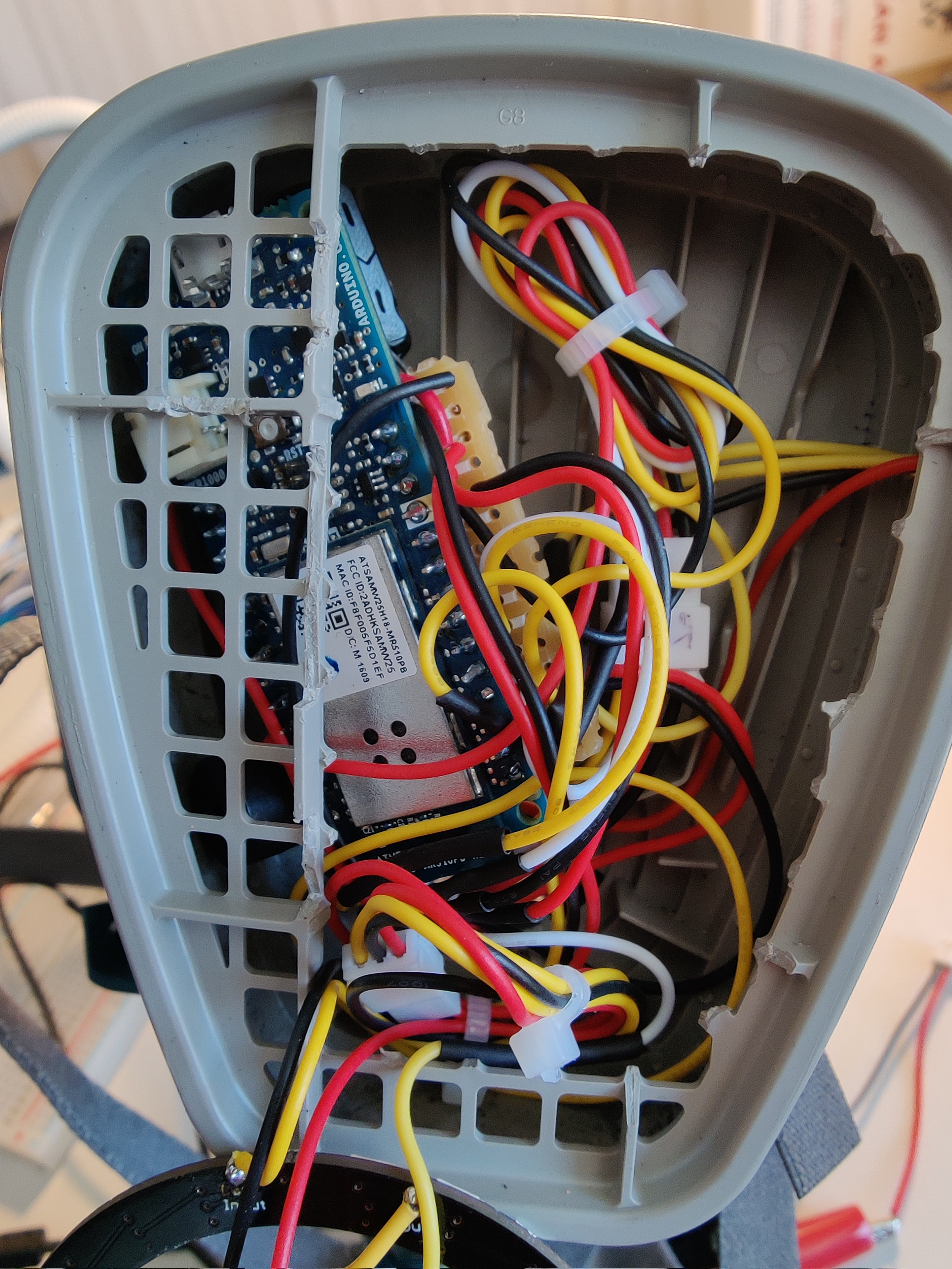
A lot of connectivity happened inside the part of the mask where my face also was. I didn’t have a main power switch, so I ran the battery connection out of the cartridge and into the facemask, letting me plug and unplug the battery without popping off the filter cover. This was also how I accessed the battery for charging. The audio power could stay connected when not charging because I had a chin mounted power switch for that. Also sharing space with my nose and mouth were a crossover cable (carried power right to left, LED signaling left to right), the speaker cable, the pressure sensor, the cable connecting the knob, the microphone, and the two extra wires I added to let the Arduino hear the microphone and disable the amp. Because I double masked when wearing this, I wasn’t bothered by it at all.

Here’s a look at the distribution board in the right filter cartridge. I had originally built this to hold two 18650s in parallel, but the project didn’t work out that way. It was really useful to have the extra space on this board when I needed to rework the LED wiring (one strip to two) and when I wanted to plumb power to the reinstalled audio hardware (which I later ripped out because of the PWM noise). In retrospect, I should have looked at this side for zip tied dead weight to cut. I could have lost the last half inch or so of the PCB, too.

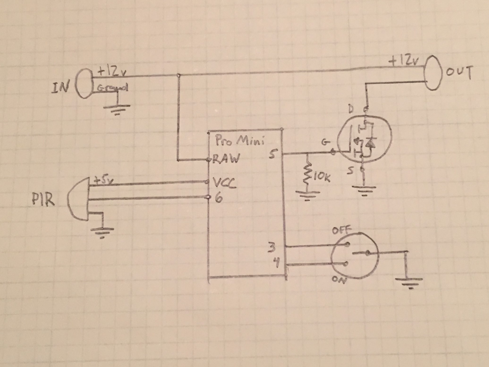
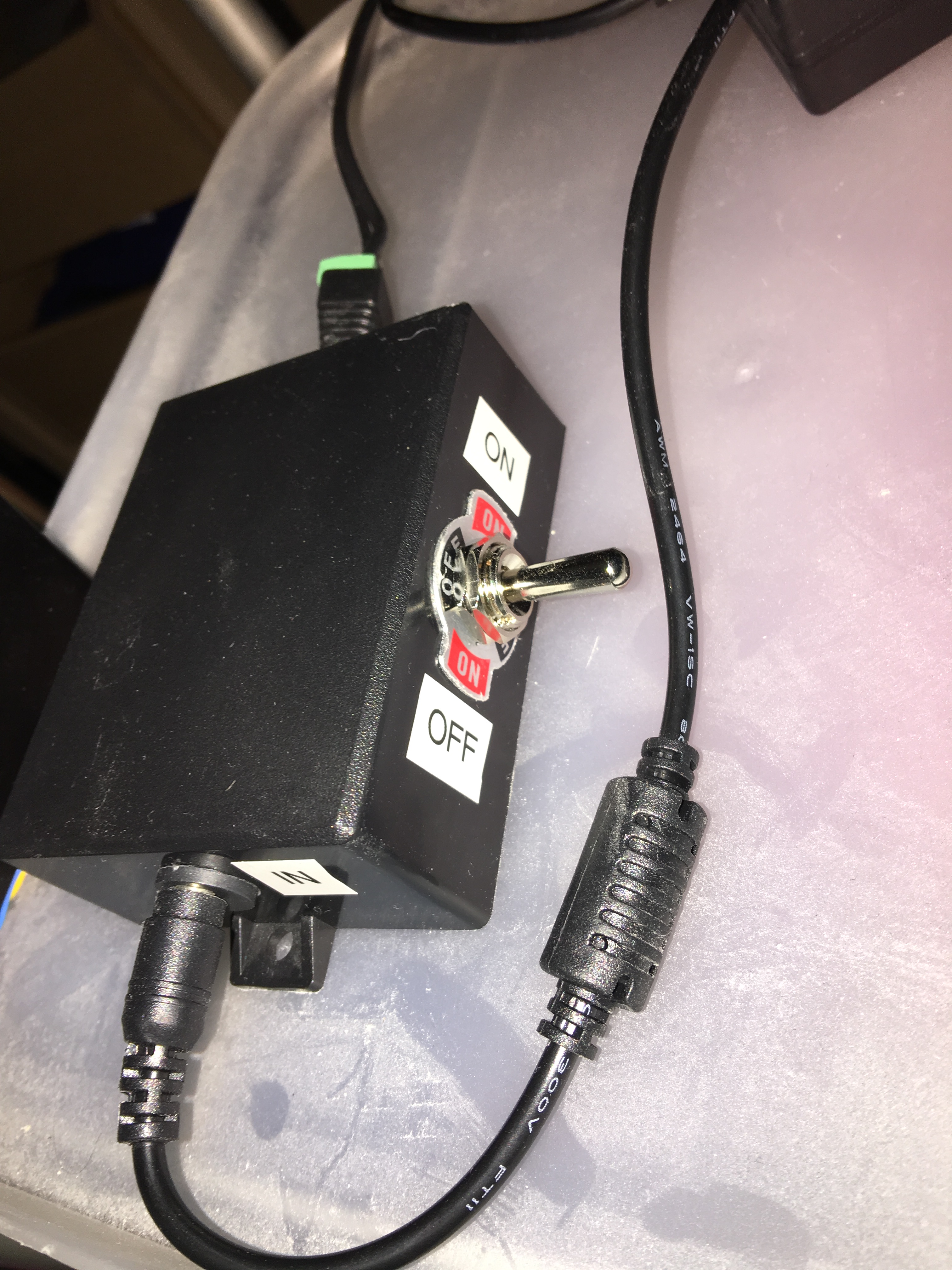
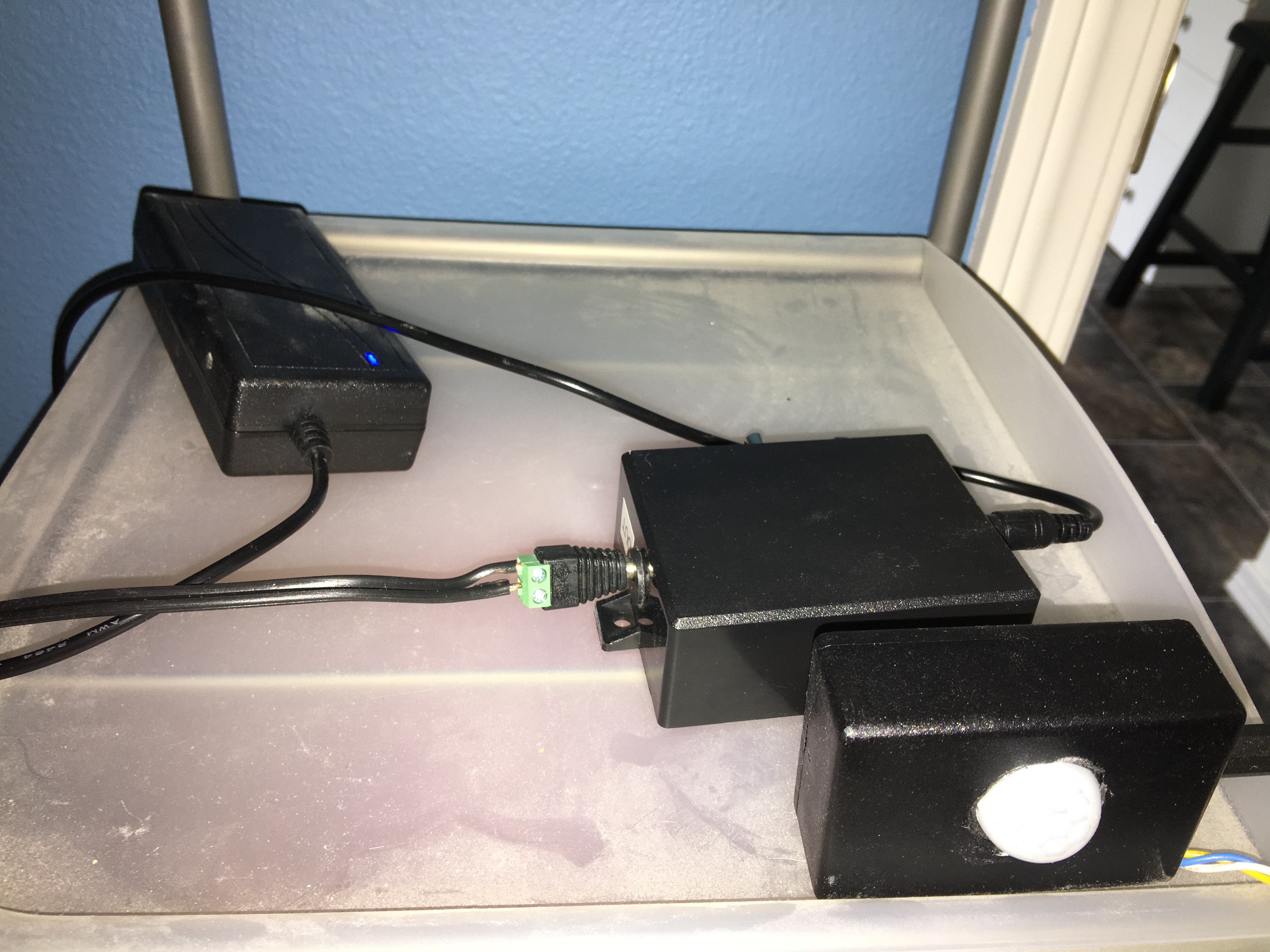
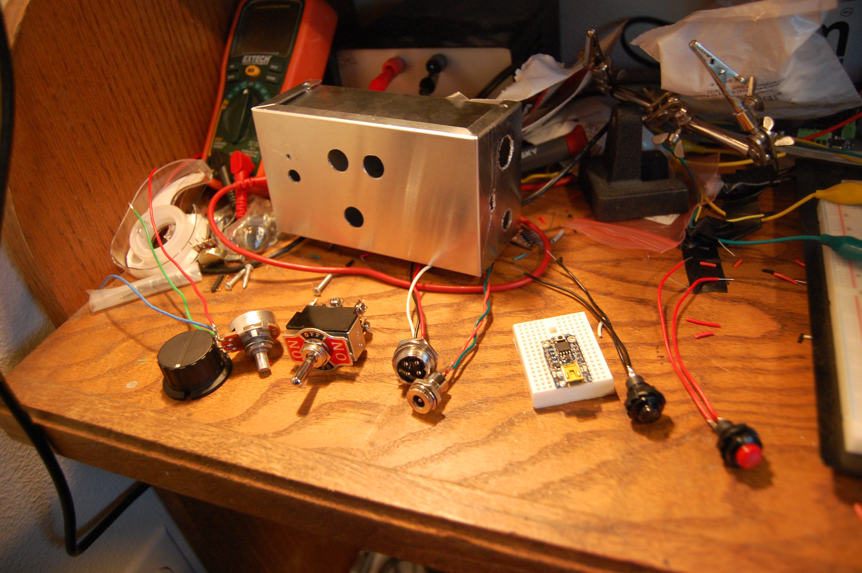
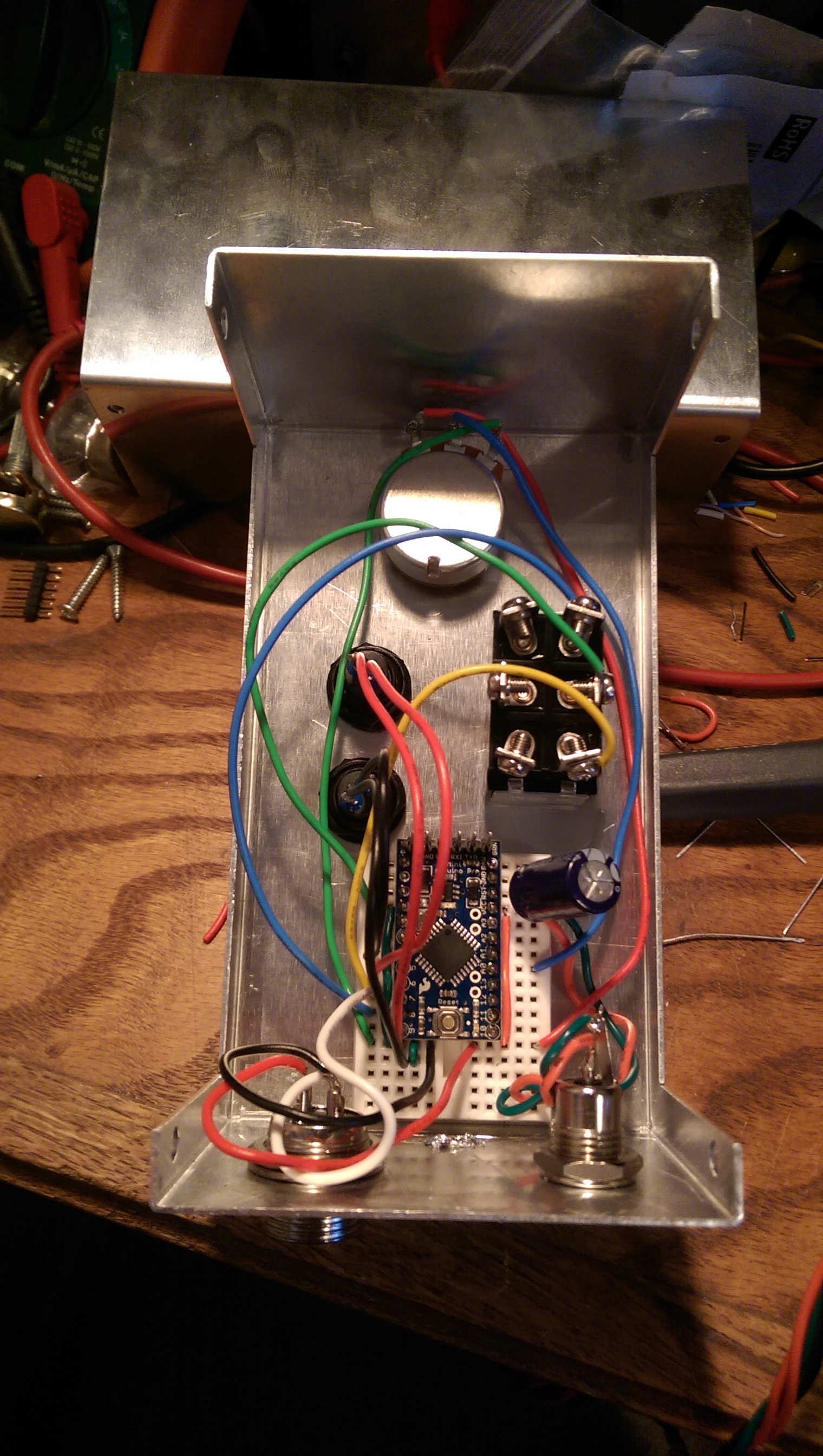
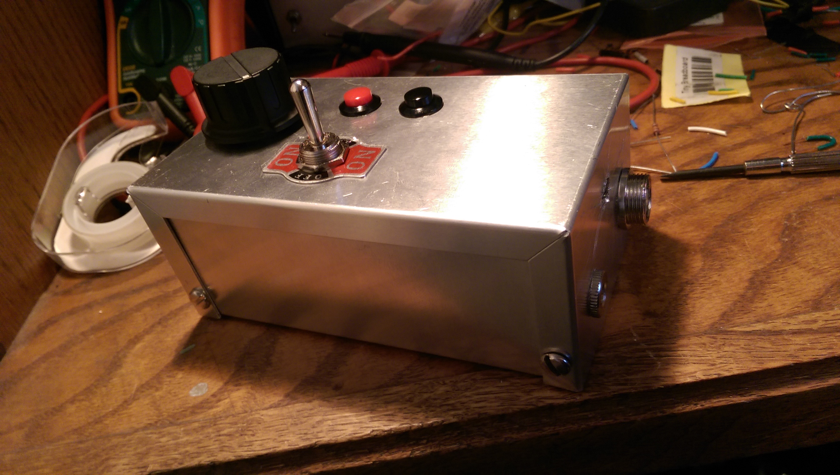
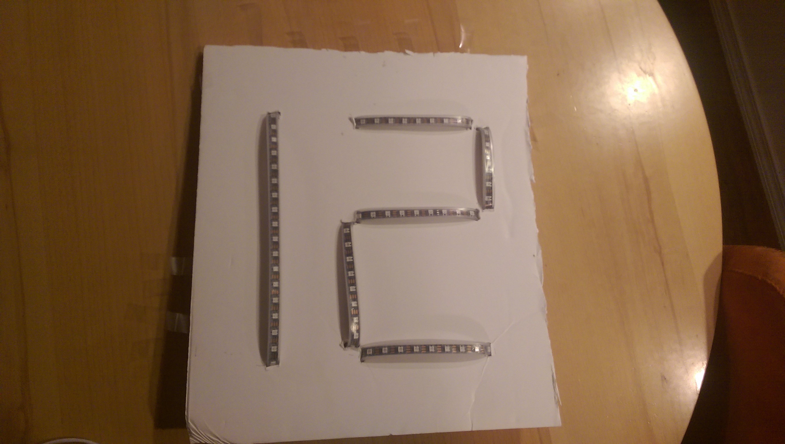
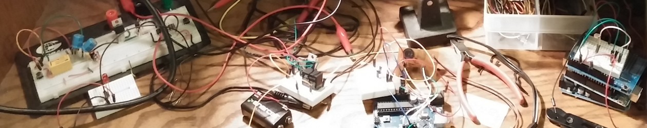
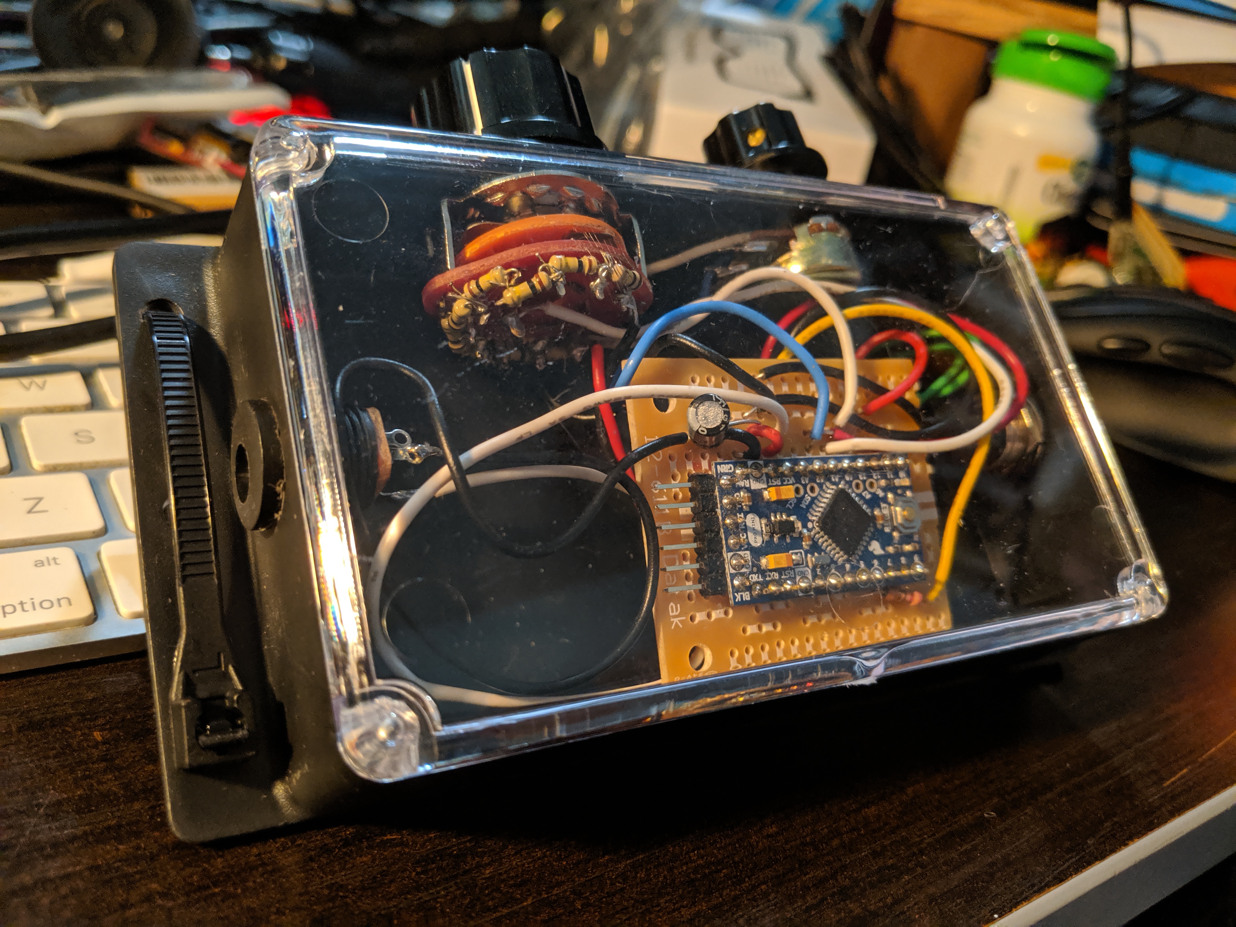
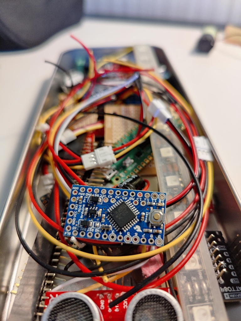
Behold the chaos of my hotel room workbench. It got even messier than this. I was really proud of how selective and correct I was about what parts and tools to bring and what to leave behind (I did bring two oscilloscopes, but they are both very small). The white cable management hose (which is full of LEDs) and the LED disc beneath it both go on my backpack. The disc has an on-board Raspberry Pi and is controlled by the same software that runs the Hawks sign. The hose has a goofy little Pro Mini-based control box with a lovely 10-way switch for behavior selection.

That cloth mask is me.
LED hose and disc installed on backpack. I have that disc at almost minimum brightness.
The resistors soldered between each position of the rotary switch mean that I can read it with just one analog pin. This project is why I added analog support to the Debouncinator.
The Arduino Pro Mini has a special place in my heart. I brought one with me just in case I decided to ditch the bulk of the MKR1000.

Post conference, I have been cleaning up the code. There were some bits that I put in a framework for and never built, and I removed most of them. One of them, I decided to complete instead: brightness adjustment. In the course of disassembling the mask for photography and also modifying and testing the software, I managed to break the mask completely. No lights, no controls, nothing. I poked at it for a couple of very disappointing days before I buckled down and got systematic. In the end, the hardware problems amounted to 3 broken solder joints. On the software side, the Arduino IDE picked up a test file that I had created in the project’s directory, and this was interfering with the correct operation of the real code. I fixed the joints, flashed the Arduino, and it’s back to full functionality.

Back to full bling capacity.

As long as I had it on the bench, I decided to pull the speaker and the amp, remove the audio power system and just run the mic off the main power. This let me also pull the chin switch and get my nice chunk of carved pencil eraser back in there. So the mask no longer makes noises, but it can still react to them, and it has only one cell to charge. Time to find a nice spot for this to live, clean off the bench, and figure out what’s next.

As usual, the code is on github.

That’ll do, mask. That’ll do.

Dog Food Timer

My newest project, and also one of my oldest, is the dog food timer. My wife and I sometimes wind up with disconnected morning or evening schedules, and this could sometimes result in the dog missing a feeding or being fed twice. There are many ways to solve this problem, but of course I chose to build an electronic one.

I first built this timer in late 2012. The first iteration used wire taped to aluminum foil to sense when the lid of the food container was opened and closed. This was read by an Arduino, which would show how long it had been since the last several times that the container was opened on a multi-line text display. I never got a photo of the text display, but this is what that foil switch setup looked like.

The giant text display had an RGB backlight, which I configured to show green/yellow/red depending on how long it had been since the dog had last been fed, and it quickly became clear that this was all we actually needed. In a knee-jerk reaction to the cost and complexity of my first overengineered solution, I took a swing at doing the whole thing with 3 LEDs and a few discrete chips (and maybe just a couple of 555 timers). Totally doable, but I wanted a little more functionality. In the end, I settled on an Arduino Pro Mini (my favorite for many years), an accelerometer left over from the robot costume project, two pushbuttons, and three LEDs. This has been in production with every dog we’ve had (two) from 2012 until this week.

The build for this project is janky as heck. The bare wires of the LEDs are loosely insulated with electrical tape, one of the buttons sticks out through a crudely dremmeled opening, both buttons are pressed toward the outside of the case by a random piece of foam… it’s just a mess. I’ve been wanting to redo it for a while.

I was thinking about this on Saturday when I realized that the Adafruit Circuit Playground Express has everything I need for this project! Its 48MHz ARM Cortex M0 is more than enough, it has a circle of NeoPixel LEDs, two pushbuttons, an accelerometer, and a piezo speaker. It’s perfect.

With all those bright LEDs, I could implement the color display in a much cooler way. This is what the new timer looks like when it’s time to feed the dog.

The clear plastic case that Adafruit sells for the Circuit Playground Express has a nice 1/4-20 (camera tripod standard) metal nut that made it trivial to attach the board to the underside of the container’s lid. So much cooler to light up the whole thing! Bonus: it shows us how much food is left in there, too.

I ported the timer code from C++ (for the Arduino) to CircuitPython. This was my first real project using CircuitPython on the Circuit Playground Express, and I found the whole system very easy to work with. Download the CircuitPython firmware, plug the board into your computer, double-click the reset button, and then drop the firmware image onto the drive that shows up. Once the file is there, the board will reboot, and then a new drive will appear. On this drive is a file named “code.py”, and every time you write to this file, the board runs it. It also offers console over serial, including an interactive environment for experimenting with the behavior of these particular libraries running on this particular version of Python. This is an amazing way to quickly build an embedded device.

Adafruit provides a Python module for their boards that makes interfacing with the hardware simple and convenient. Create an instance of the module, then just read the property “button_a” to know if the button is being pushed or “acceleration” to get a tuple of x, y, and z acceleration. I couldn’t find an obvious abstraction for button clicks, but I found a pattern that I like. One feature of their module that I did not find in any of the examples is cp.were_pressed. This is a property that returns the set of buttons that are being pressed. Combined with a little bit of set arithmetic, this gave me rock solid debounced button clicks.

As always, the full code for this project is on github: https://github.com/erickhammersmark/dogfoodtimer. Here’s the new timer in action.

Automatic closet lighting

When I redid my closet, I went all out and installed over-closet lighting. It has this lovely soft glow that really classes up the IKEA. These lights have two drawbacks. First, their tiny switches are all the way up on the bases of the lamps, and there are six of them. Super inconvenient. Second, both sets of three lights burned out their power supply within the first year.

After having one of the supplies sitting in my workshop for years, I finally gave up on it and ordered some replacement supplies. 12v @ 60W x 2, just like the lights came with from IKEA. They even came with screw terminal 2.1mm jacks, which are very handy.

I gutted one of the IKEA supplies and retrofitted it with a 2.1mm jack. When I tested this with my closet lighting, I found that time and/or PSU death had cost me more than half of the bulbs. The new supplies were fine, but when I looked closely at the bulbs, I saw that they are 20W each. No wonder the original supplies burned out, they were running at their maximum rated capacity 24/7! Who can reach those six tiny switches? So I replaced them all with LEDs. I can run all 6 lamps off of one of the new supplies, they look great, and I can leave them on all the time without guilt. But that wouldn’t be any fun at all.

I picked up a 5-pack of PIR motion sensors (data sheet). This was my first experience with pyroelectric IR sensors, and I was surprised at how easy they were to work with. The modules I bought had a very simple 3-pin connector (+5, ground, and signal) with two on-board POTs for adjusting sensitivity and re-fire delay. I cranked sensitivity all the way up and re-fire delay all the way down and I was good to go. Once these things see a person, the signal pin goes high for the length of the delay. Since I’m not doing anything fancy with how I read them, this adds the length of the delay to my “lights off” time (which is 10 seconds).

schematic

The design is pretty simple. I built this project around an Arduino Pro Mini 5v/16MHz, my go-to one-off “production” build board. I have one of these running the sensors in my garage (post on that project is pending) and one running each of the NeoPixel control panel boxes in my kids rooms. Given how often I use these boards, I made a really boneheaded mistake when I moved this project from breadboard to protoboard: I wired Vin (which is 12V) directly to VCC (instead of RAW) on the pro mini. This kills the pro mini. Twice. SMH.

As you can see in the schematic, 12v in is wired directly to 12v out. I use an N-channel MOSFET to switch the output’s ground connection. This is a great transistor for this kind of project, because you can switch it all the way on with 5v directly from a digital I/O pin on the Arduino. In addition to the PIR sensor, there’s a physical switch that can also control the behavior of the lights. I’m using a big fat 3-position DPDT switch with one direction for ON, one for OFF, and the center position to allow the sensor to control the lights.

switch

system

Check out this amazing demo video, wherein I walk into my closet and then walk right back out again.

NeoPixel control panel

The holiday season is over, Christmas has been torn down, and a new year has begun. It’s time to figure out what to do with that reel of Neopixels that I bought last year. They made a fun little window decoration, but I don’t want to leave them there year round. I have it in my head to use some of them to make custom lighting for my sons’ bunk beds, and the boys are keen on this idea, too. After a trip to Radio Shack, we have all the parts we need.

2015-01-05-00.39.03

For each of two control boxes, one each of:

  • Enclosure
  • 50k linear pot
  • 1/4″ shaft knob
  • Red momentary switch
  • Black momentary switch
  • 2.1mm DC jack
  • 4-pin mic jack (panel mount)
  • 4-pin mic plug (in-line)

And I already had some other bits and pieces laying about:

  • DPDT center-off toggle switch
  • 5v power supply
  • mini breadboard
  • microcontroller

NB: A Trinket is pictured, but I decided that I want more inputs, I built these using Pro Minis.

2015-01-05-22.22.22

2015-01-05-21.35.49

I turned out to have drilled the hole for the pot’s little stabilizing pin on the wrong side, which meant that I had also wired it backwards, but it all worked out in the end. It’s not the kind of precision-routed beauty that my father taught me to love, but it’s not a complete rat’s nest, either.

2015-01-05-21.41.41

Assembly is straightforward. The plastic enclosure took 1d4 of damage at the hands of the drill press, but a little superglue fixed it right up. The behaviors will be pretty simple: use the toggle switch to select between two modes (solid color and disco mode), use the knob and buttons in each mode to adjust the settings for that mode. In solid color mode, pushing the red button will let you use the knob to adjust the color, and pushing the black button will let you adjust the brightness. In disco mode, pressing the red button will cycle through display modes (ripped straight from Adafruit’s strandtest sketch) and the knob will adjust the color where appropriate. The schematic couldn’t be simpler.

neopixel_control_box_schematic

The only tricky thing is the software: I want to use the various strandtest behaviors (color wipe, theater chase, rainbow cycle, etc.), but I don’t want to strand the user interface for the entire length of a behavior cycle. For example, theaterChase() looks like this:

//Theatre-style crawling lights.
void theaterChase(uint32_t c, uint8_t wait) {
  //do 10 cycles of chasing
  for (int j=0; j<10; j++) {
    for (int q=0; q < 3; q++) {
      for (int i=0; i < strip.numPixels(); i=i+3) {
        //turn every third pixel on
        strip.setPixelColor(i+q, c);    
      }
      strip.show();
     
      delay(wait);
     
      for (int i=0; i < strip.numPixels(); i=i+3) {
        //turn every third pixel off
        strip.setPixelColor(i+q, 0);        
      }
    }
  }
}

https://github.com/adafruit/Adafruit_NeoPixel/blob/master/examples/strandtest/strandtest.ino

The value of “wait” is 50, which means that this function will take approximately 50 * 3 * 10 = 1500ms = 1.5 seconds to run. Unless I make my UI interrupt-driven (which is not my usual way of building UIs in Arduino), this will cause up to a 1.5 second delay between pressing a button and seeing any result. For some of the other modes, it’s worse. theaterChaseRainbow() would take more like 38 seconds. Clearly, this will not do.

Enter the global state rewrite! Now, theaterChase() looks like this:

//Theatre-style crawling lights.
void theaterChase() {
  if (i == 0) {
    for (i=0; i < strip.numPixels(); i=i+3) {
      //turn every third pixel on
      strip.setPixelColor(i+q, getColor());
    }
    strip.show();
    delay(wait);
  } else {
    for (h=0; h = 3) {
      q = 0;
      j += 1;
      if (j >= 10) {
        j = 0;
      }
    }
  }
}

It only calls delay(wait) once peer loop(). All of the local state has become global state, so not only do I get to do other work while I’m in the middle of a theater chase cycle, I can also modify its behavior mid-run, changing the color of the color wipe or theater chase behaviors.

After rewriting all of the modes this way, I’m ready to test.

A handful of zip ties later and I have some delighted children!

2015-01-08-20.10.27
2015-02-01-20.27.48

#12s

The Seahawks play the Packers tomorrow for the NFC championship, so here’s a quick “12th man” project. I took a square of foam core board, cut some slots at the ends and vertices of the digits 1 and 2, and threaded these slots with a 100-light NeoPixel strip.

2015-01-17-23.34.33 2015-01-17-23.34.51

Add a little support hardware and you have one fancy window decoration.

2015-01-17-23.40.11

This connects power from the strip to +5v and ground on the Uno and the data pin on the strip to digital pin 6. The 1000uF cap across the power and 470ohm resistor on the data line are per Adafruit’s recommendations. If I decide to keep it for next season, I’ll probably mount a Pro Mini or a Trinket to the back of the foam board so that all I’ll need to do is connect it to power.

The code is very simple, adapted from the “theaterChase” function in the NeoPixel example sketch.

#include <Adafruit_NeoPixel.h>

#define PIN 6
#define NUM_PIXELS 100
#define DELAY 50

Adafruit_NeoPixel strip = Adafruit_NeoPixel(NUM_PIXELS, PIN, NEO_GRB + NEO_KHZ800);

uint32_t green = strip.Color(0, 255, 0);
uint32_t blue = strip.Color(0, 0, 255);
uint32_t color = green;

void setup() {
  strip.begin();
}

void loop() {
  for (int q=0; q < 3; q++) {
    for (int i=0; i < NUM_PIXELS; i=i+3) {
      if (color == green) {
        color = blue;
      } else {
        color = green;
      }
      strip.setPixelColor(i+q, color);    
    }
    strip.show();
     
    delay(DELAY);
     
    for (int i=0; i < NUM_PIXELS; i=i+3) {
      strip.setPixelColor(i+q, 0);        
    }
  }
}

And here it is in action. Go Hawks!

Does the Christmas tree need water?

It seems that more and more people are putting up fake Christmas trees, these days. Well, not so at the Hammersmark home. We used to go cut down our own, but, this year, we bought it from the Boy Scout lot nearby. We got a beautiful 7′ Nordmann, managed to squeeze a couple of hours of tree-trimming into our ridiculously busy holiday schedule, and now I get the job of keeping it from burning our house to the ground.

I have a simple system that I’ve used for several years to keep me from having to get down on my hands and knees with a pint glass full of water. It’s a length of 3/4″ plastic tube duck taped to a funnel. The funnel is connected to a heavy duty twist tie, which I use to hang it from the tree like the biggest, ugliest ornament ever. I route the tube to the tree stand, then I pour water (slowly) into the funnel and trust that it’s both making its way into the tree stand and not overflowing the basin. I have, in the past, been mistaken.

moisture_sensor

Enter: as-yet-unused garden automation supplies. Last year, I bought a six-pack of cheap moisture sensors from eBay. I also picked up (from Sparkfun) a couple of 12v 3/4″ electric valves, a handful of Arduino Pro Minis, some N-power MOSFETs and some relays. I never did get around to automating the garden, so I still have all of this stuff sitting around the workshop. I decided to put some of it to use (and learn how it works) by building a water level sensor for my Christmas tree stand.

sensor

The sensor is brilliantly simple. It comes in two parts: the sensor strip and a small driver board. The driver board offers 4 pins back to the microcontroller: Vcc, ground, digital signal, and analog signal. The digital signal just runs a comparison on the analog value, controllable by a variable resistor mounted on the board. The analog signal just gives you a voltage somewhere between 1/3 Vcc and Vcc. Though it is intended to go into moist soil, it is perfectly happy reading a half full glass of water.

board

I had a few empty plastic Christmas ornaments that I picked up thinking I might stick some Neopixels in them. One of them was big enough to hold a Pro Mini, so I soldered 5 LEDs to 5 digital pins, soldered 1k resistors to the negative leads of the LEDs, soldered these all together and then connected this to ground. I wired in the sensor board and a power supply, ran all the wires out the top of the ornament, and my water level sensor was ready to go!

3bars

I looped the sensor strip’s cable over part of the tree stand and just let it dangle in the water. When I first installed it, the tree hadn’t had any new water since the previous day, but the level wasn’t anywhere near the base of the trunk. I adjusted the height of the sensor until this lit up 3 of my 5 LEDs. After pouring in a pint of water, the sensor lit up all 5 of my LEDs. Success!

5bars

Next step: Use this to trigger a system that automatically waters the tree from a reservoir. Now I just need another one to monitor the level in THAT…

UPDATE: I am sad to report that immersion in my tree-water (or, perhaps, in any water) causes the moisture sensor to quickly deteriorate. This project worked perfectly when I first installed it. By the following morning, it would only ever read 2 or 3 LEDs full. I pulled the sensor out this evening to discover this mess right here:

2014-12-10-21.58.16

After cleaning up the corroded probe, I found I could get more-or-less 3 reliable signals: dry, some water, and fully immersed. I reworked the code a little bit to cope with only 3 signal levels and am, for the time being, back in business.

intree

Tiny robots are the best robots

I have long admired Actobotics, a “robotics building system based around extruded aluminum channels, gears, precision shafts, and ball bearings”. It’s like a beautiful, heavy-duty, precision-crafted Erector set. For some reason, I never bought any. It’s kind of expensive, and there are so many parts (470, at least when SparkFun started carrying them last year) that I didn’t really know what to buy.

So, I bought a kit! I bought the ActoBitty 2, ROB-13047. It’s a little two-motor tricycle robot, with clips for mounting an Arduino Uno and just enough room left over for some sensors. It comes with motors, wheels, a little fixed caster, and a battery case, all of it mounting on about 4″ of that lovely aluminum channel. Thirty bucks at SparkFun.

2014-10-27-20.25.40

Assembly was totally straightforward, though it didn’t come with any printed instructions, just a link to a video of someone putting one together (as it turns out, they have written instructions on their website). After a lot of pausing (the video was sped up in many places), I had a tiny robot. The kit doesn’t come with a microcontroller or any other way to control the motors, but it does come with a place to snap in an Arduino Uno, so I did. I didn’t have any motor shields on hand, so I just threw a couple of MOSFET transistors into a tiny breadboard and patched that into the Arduino, and then I could drive the motors.

2014-10-27-22.51.19

This worked well for driving either or both motors forward, but could not drive them backward. To do that, you need something like an H-bridge, which can apply power to the motor in either direction. If you can’t be bothered to put together an H-bridge (I couldn’t), you can buy a nice Arduino shield that wraps an H-bridge IC. I am very fond of the Adafruit Motorshield but, because they were backordered at the time when I was doing this project, I wound up using a cheap clone instead.

2014-11-15-15.47.38

OK, so I can write a program to make the wheels turn in the directions and at the speeds that I desire. Awesome. What else?

By this point, Halloween was done, and my Parallax Ping was free. I threw that into a tiny breadboard and, for the first time (I think), peeled the sticky backing off of the back of one of those tiny breadboards and stuck it right onto my beautiful, precisely machined aluminum channel.

2014-11-02-21.59.02

If I want to take it off, I’m sure I can scrape that adhesive off of the aluminum. It’s aluminum: it will always be beautiful.

Now my tiny robot can see the world!

The algorithm is super simple:

void loop() {
  int distance = measureDistance();
  if (distance < DISTANCE_THRESHOLD) {
    rotate_left();
  } else {
    forward();
  }
}

This works fine for getting around, unless one of the wheels gets stuck on something. It seems to have trouble seeing the oven; maybe it’s the angle.

Robot Costumes

For Halloween 2012, I built my kids a pair of robot costumes. I started with nothing but my sci-fi sensibilities and the physical constraints of a 6 year old and a 4 year old. This is what I came up with:

2012-10-31-20.49.57

lost_in_space

From the beginning, I knew that the arms and legs had to be 4″ dryer vent tubing. Danger, Will Robinson!

Some of the ideas are based on materials that I happened to have on hand. Glowing LED sunglasses that my older son had won in a contest, an LCD display that I had leftover from another project, etc. Once I realized I needed to make two of these (initially, my 4 year old was disinterested in the costume), I scrapped most of the ideas that relied on expensive components that I already had one of, but not two of. I’m looking at you, LCD display.

The most important thing was that the costume look busy. Buttons to press, switches to flip, der blinkenlights… think W.O.P.R. or Dr. Theopolis. To accomplish this, I decided to build a grid of LEDs in the middle, which I could then turn on and off at random. Very W.O.P.R.-esque.

I also wanted this costume to do something useful. Since I wasn’t planning on building anything strong enough to hold the candy bucket or transport my children along the sidewalk, I decided that a built-in flashlight was the way to go.

OK, minimum requirements are now met. What else?

Noise. I chose two audio features for these costumes. First, a robot voice changer, which takes everything spoken into a mic and renders it Dalek-sounding and unintelligible. And second, a robot walking sound, which it should only make when they walk.

This was the final list of features:

  • Robot voice changer
  • LED grid
  • Robot walking noise
  • Flashlight
  • Glowing outline

2012-10-27-15.29.23

The bodies were constructed out of cardboard, spray-painted silver. The backs were open and got taped closed when the costumes were worn. The arms and legs were 4″ flexible dryer vent hose, and the legs were taped to a pair of shorts, which were covered in foil tape. Aesthetically, they came out just as I had envisioned, looking every bit the old fashioned sci-fi robot. Functionally, this design was flawed: my younger son didn’t have enough freedom with his legs to climb steps, which was a problem when trick-or-treating in our neighborhood. If I had it to do over again, I would have cut the boxes off at the waist. I also would have done something to decorate the neck hole, and maybe provided some headgear.

I had already settled on the Arduino Uno as the platform for this project (mostly because I already had some), and those totally suck at making noise. In the end, I did two things: first, I bought a couple of cheap voice changer toys, which I ripped apart and bolted into my robots (for cardboard and plastic values of “bolted”). The guts of the toy were taped up inside the body, the microphone was mounted on top, and the speaker was mounted in front. Hot glue secured the external components, and the red covered switch in the upper corner controled the toy’s battery. The toy supports several voice changing modes, but I didn’t expose that switch. I left it set to “robot”. I also used the High-Low Tech Group’s PCM audio library to produce sound from the Arduino. I found a nice “robot walking” sample online.

2012-10-31-20.42.49

I built proto shields to hold all of the non-Arduino components I needed for the LED grid and the robot walking sound. These included resistors to limit current though the LEDs, the accelerometer for detecting walking, and leads to connect to the speaker, the LEDs, and the relevant switches. These worked out great, but I should have socketed the accelerometer boards, since I knew I’d want to reuse them for other projects.

2012-10-31-20.39.18

The 4 x 4 grid of red LEDs below the speaker are poked through the cardboard and hot glued from behind. They have two modes of operation: random flashing or always on. The switch on the left side (wearer’s left) controls the LEDs. It’s a 3-position switch: center-off, up all-on, down flashing. The LEDs are wired in 3 groups (randomly selected as I was soldering them), and each of these groups is wired through a 100 ohm resistor to a pin on the arduino. The groups are randomly switched on and off (in the “flashing” mode), which produces an effect that looks just right to me.

The big knife switch on the right (wearer’s right) controls the walking sound. This is my favorite feature of the costume. I used an MMA7361 accelerometer board in high sensitivity mode to detect motion, simply by summing up all of the movement on all 3 axes and deciding that walking was occuring if those all added up to more than an empirically determined threshold. When motion was detected, the Arduino would use the PCM audio library to play the robot walking sound through the speaker.

2012-10-27-19.20.30

Once I had it all built, it became clear that the walking noise was not loud enough, especially if both the voice changer and the walking sound were active at the same time (they shared the speaker). I built a little LM386-based audio amplifier to beef up the walking noise, which made a big difference.

The walking light is built from the head of an LED flashlight, controlled by the switch near the bottom. It angles slightly down, and is secured with hot glue. This is the “useful” feature.

2012-10-31-17.44.43

The front and top of the costume are edged in el wire (red for one build, blue for the other). This looked really great when we were out trick-or-treating in the dark! This is the only feature that is not switched externally. I used the el wire controller to switch these on as the child was loaded into the costume.

In all, this costume had 5 different power systems. A bank of 4 AAs powered the Arduino, which powered the LEDs and provided the input for the audio amplifier. The amp used a 9v battery. The walking light used a single D cell. The voice changer toy had its own (tiny!) 12v battery, and the el wire came with its own battery-powered driver (2 AAs). If these costumes were going to get enough use to ever need to change any of the batteries, I would have looked at driving most or all of it from a single power source. Since they were only ever going to be worn to one Halloween party and one night of trick-or-treating, I didn’t bother.

2012-10-31-20.38.08

The costumes did pretty well in the field. My older son (6, at the time) had no trouble getting around or using his arms, though he did have a little trouble squeezing himself into the thing. My younger son (3-almost-4, at the time) had no trouble getting in, but the body of the costume came down so low, he couldn’t raise his knees to climb steps. And the body was so wide, he could not touch his hands in front of himself, had trouble feeding himself, and could not reach to push himself up when he fell. Which he did. A lot. By the end of the night, one voice changer had stopped working, and one group of LEDs had gone out (and then later come back on). Considering the abuse that a 6 year old and a not-quite-4 year old can deliver, I was very pleased with these results.

Halloween Automata

Halloween has long been a favorite holiday, and I love the opportunity it provides for implementing fun and otherwise useless physical projects. This year, since my kids were both wearing store-bought costumes (and refused my offer for hand-crafted wooden swords, much to my surprise), I thought I’d do a little work on the decorations. My wife picked up a full sized skeleton to sit on our front porch, so I decided to give it some spooky red eyes and to breathe a little life into it by rocking its chair.

There are many examples on the web (Makezine’s, for example) of doing this kind of project with a windshield wiper motor. They’re strong, they run on 12v, and they run at around the right pace. I didn’t have a windshield wiper motor, but I DID have some crappy DC motors that I’d salvaged from a dead “Black Friday” printer, so I gave it a go with one of those.

2014-10-31-21.09.54

To secure the motor, I clamped it to a wooden board, then zip tied the board to a fold-up sawhorse. To interface with the motor, I used InstaMorph. InstaMorph is a polyester thermoplastic that melts nicely in the boiler water from my espresso machine. I used this to form a spindle with a flange at one end, then I jammed the shaft of the printer motor (which had a small gear attached) into the other end. I pressed the plastic down around the gear as it cooled, and the result was a spindle that was firmly attached to the motor. I drilled a hole through the middle, tied some nylon twine through the hole, and I was ready to rock my chair.

2014-10-30-20.18.35

It turns out that we had a small skeleton from Halloweens past, and my son had the wonderfully creepy idea to have the larger one cradling the smaller one as they rock. Using some small panel-mount LEDs and many feet of 22ga hookup wire, I gave them both glowing red eyes. The bundles of wire exiting the bases of their skulls gives the skeletons a lovely H. R. Giger vibe.

2014-10-31-21.09.48

The heart of the project is an Arduino Uno. I can’t say enough wonderful things about this little workhorse. It’s not the fastest thing you can get at its size, nor is it the most capable, but they’re cheap, they’re robust, and the community support for them is outstanding. In early incarnations of this project, I combined my Uno with an Adafruit Motorshield. This made driving the motor in two directions trivial, but it turned out to be consuming too many of the digital pins. Since I wound up with a rocking methodology that did not require me to spin the motor in two directions, I swapped out the motorshield for an N-channel MOSFET. The transistor, the rest of the hardware to support the motor, an on/off switch, and an extra header full of ground connections all got soldered onto a protoshield. The eyes insert into 4 of the digital pins and 4 of the ground connections on the extra header, and another digital pin (as well as the +5v and one more ground header) went to a Parallax Ping.

2014-10-31-21.10.19

I threw a header onto a fragment of a prototyping board, just to have somewhere portable to plug the sensor into. I wired about 10′ of cat5 (just 3 conductors) to that board, and I also soldered some short lengths of 22ga wire to the other end of the cat5. My cat5 is much thinner than 22ga and inserts poorly into breadboards and headers.

Here’s a quick walkthrough of the whole system, laid out in my dining room on the day before Halloween:

Halloween 2014 automaton – feature complete

Installation was straightforward. I positioned the sawhorse behind the rocking chair, looped the twine over one of its slats, and programmed the motor for half a second on, three seconds off. This produced a noisy, spastic rocking that was in no way awesome, but was entirely good enough. The eyes, on the other hand, WERE pretty awesome.

This was a really fun project, and I was able to put it together using only components that I already had laying around my workshop. I was really pleased that I was able to produce an acceptable rocking motion using only a dc “hobby” motor, and the InstaMorph worked wonderfully for physically interfacing with the motor. And it looked super creepy in the dark.

2014-10-31-19.16.30