
When I redid my closet, I went all out and installed over-closet lighting. It has this lovely soft glow that really classes up the IKEA. These lights have two drawbacks. First, their tiny switches are all the way up on the bases of the lamps, and there are six of them. Super inconvenient. Second, both sets of three lights burned out their power supply within the first year.
After having one of the supplies sitting in my workshop for years, I finally gave up on it and ordered some replacement supplies. 12v @ 60W x 2, just like the lights came with from IKEA. They even came with screw terminal 2.1mm jacks, which are very handy.
I gutted one of the IKEA supplies and retrofitted it with a 2.1mm jack. When I tested this with my closet lighting, I found that time and/or PSU death had cost me more than half of the bulbs. The new supplies were fine, but when I looked closely at the bulbs, I saw that they are 20W each. No wonder the original supplies burned out, they were running at their maximum rated capacity 24/7! Who can reach those six tiny switches? So I replaced them all with LEDs. I can run all 6 lamps off of one of the new supplies, they look great, and I can leave them on all the time without guilt. But that wouldn’t be any fun at all.
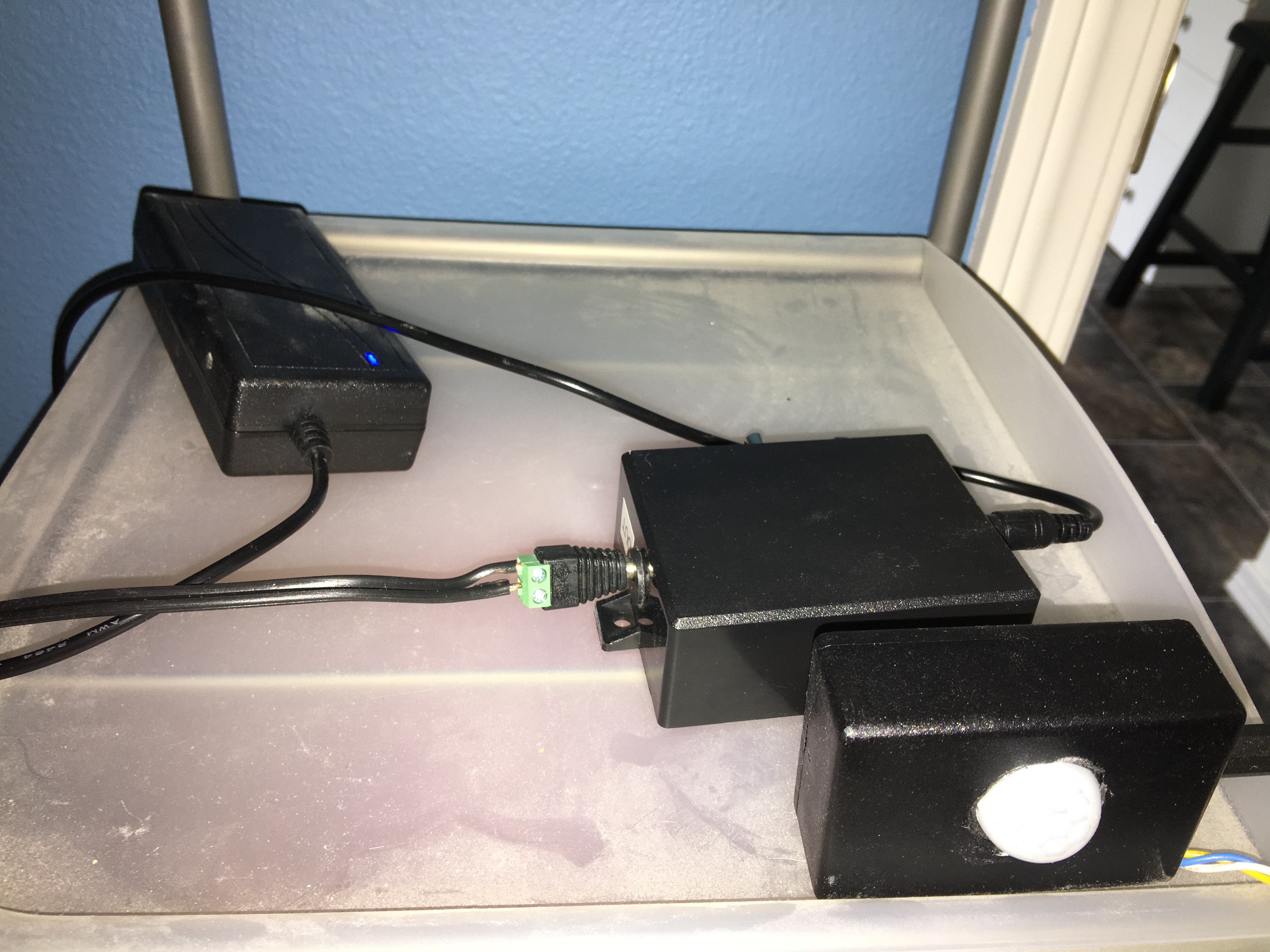
I picked up a 5-pack of PIR motion sensors (data sheet). This was my first experience with pyroelectric IR sensors, and I was surprised at how easy they were to work with. The modules I bought had a very simple 3-pin connector (+5, ground, and signal) with two on-board POTs for adjusting sensitivity and re-fire delay. I cranked sensitivity all the way up and re-fire delay all the way down and I was good to go. Once these things see a person, the signal pin goes high for the length of the delay. Since I’m not doing anything fancy with how I read them, this adds the length of the delay to my “lights off” time (which is 10 seconds).
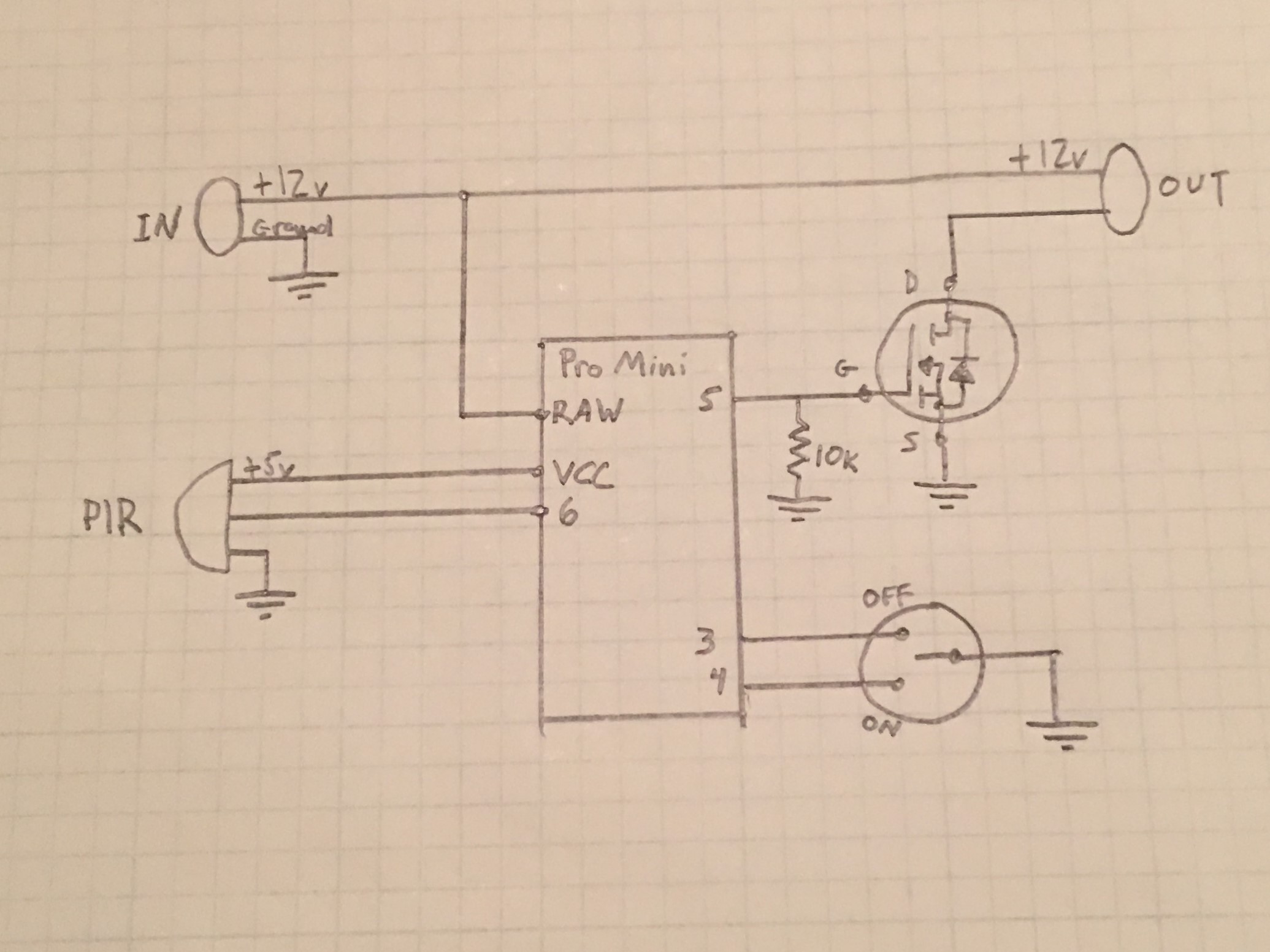
The design is pretty simple. I built this project around an Arduino Pro Mini 5v/16MHz, my go-to one-off “production” build board. I have one of these running the sensors in my garage (post on that project is pending) and one running each of the NeoPixel control panel boxes in my kids rooms. Given how often I use these boards, I made a really boneheaded mistake when I moved this project from breadboard to protoboard: I wired Vin (which is 12V) directly to VCC (instead of RAW) on the pro mini. This kills the pro mini. Twice. SMH.
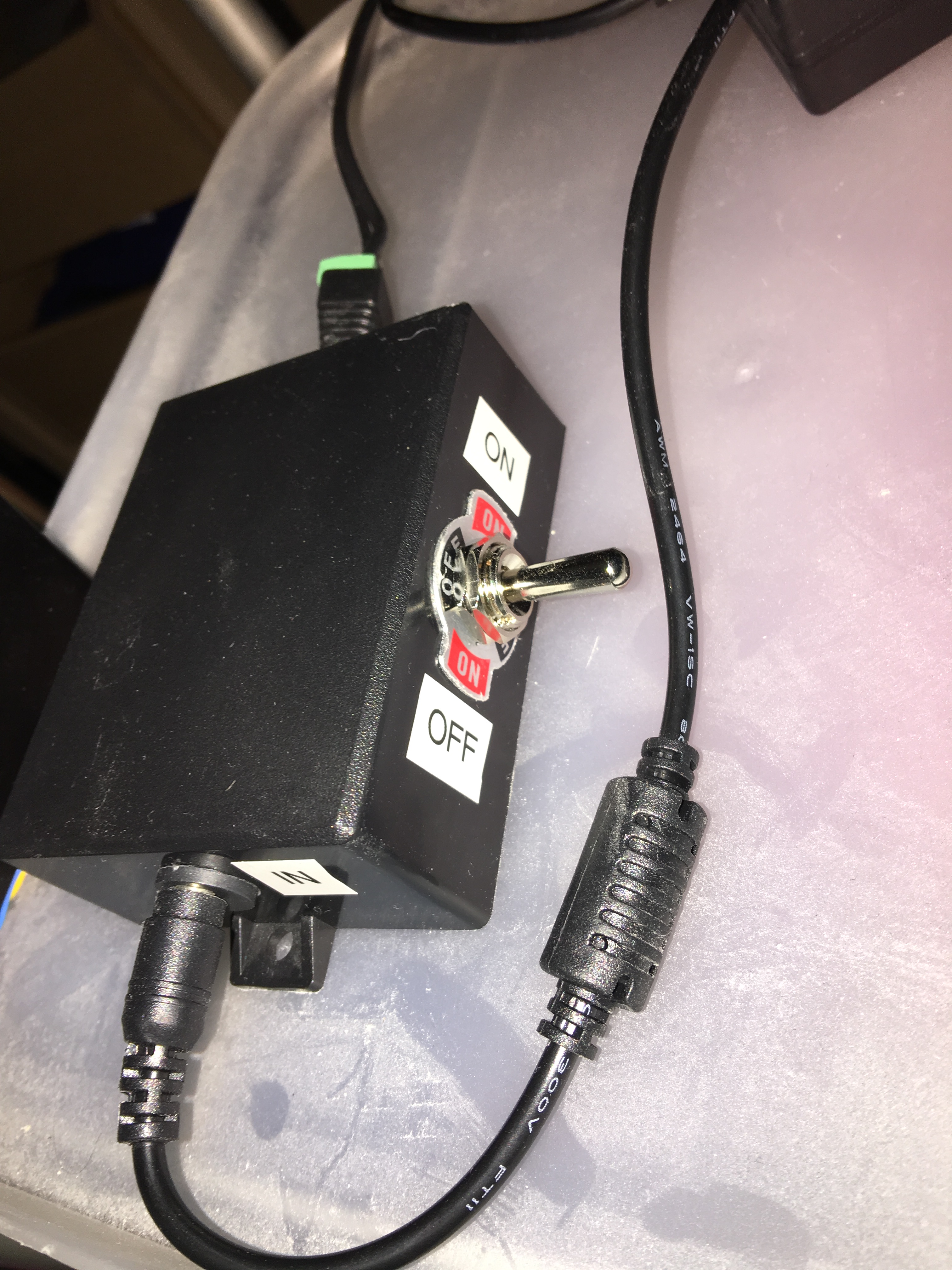
As you can see in the schematic, 12v in is wired directly to 12v out. I use an N-channel MOSFET to switch the output’s ground connection. This is a great transistor for this kind of project, because you can switch it all the way on with 5v directly from a digital I/O pin on the Arduino. In addition to the PIR sensor, there’s a physical switch that can also control the behavior of the lights. I’m using a big fat 3-position DPDT switch with one direction for ON, one for OFF, and the center position to allow the sensor to control the lights.
Check out this amazing demo video, wherein I walk into my closet and then walk right back out again.
