Christmas hardware! A full reel (4 meters) of 60 LED NeoPixel strip and a big pile of supporting bits and pieces for building, among other things, some kind of holiday lighting installation. I might put these on the tree, I might use them to decorate the outside of the house, or maybe I’ll just use them to add red and green glows all over the place. Other projects on deck for the months of November and December include an automatic tree watering system and IP-accessible garage door opener.
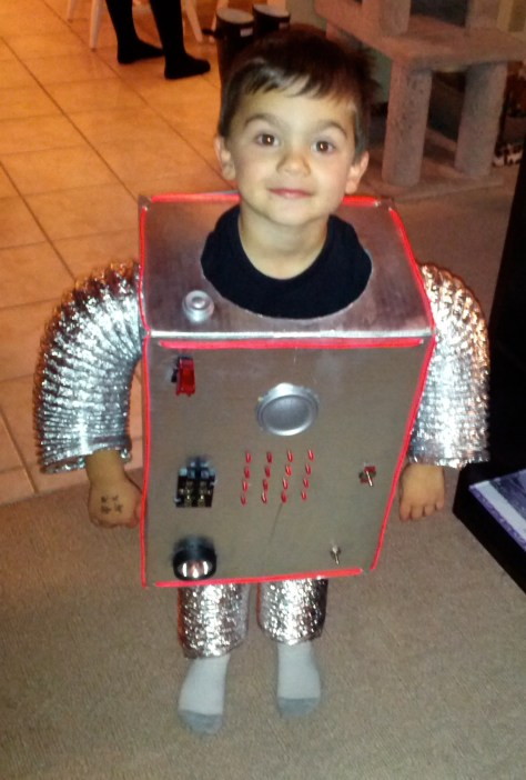
For Halloween 2012, I built my kids a pair of robot costumes. I started with nothing but my sci-fi sensibilities and the physical constraints of a 6 year old and a 4 year old. This is what I came up with:
From the beginning, I knew that the arms and legs had to be 4″ dryer vent tubing. Danger, Will Robinson!
Some of the ideas are based on materials that I happened to have on hand. Glowing LED sunglasses that my older son had won in a contest, an LCD display that I had leftover from another project, etc. Once I realized I needed to make two of these (initially, my 4 year old was disinterested in the costume), I scrapped most of the ideas that relied on expensive components that I already had one of, but not two of. I’m looking at you, LCD display.
The most important thing was that the costume look busy. Buttons to press, switches to flip, der blinkenlights… think W.O.P.R. or Dr. Theopolis. To accomplish this, I decided to build a grid of LEDs in the middle, which I could then turn on and off at random. Very W.O.P.R.-esque.
I also wanted this costume to do something useful. Since I wasn’t planning on building anything strong enough to hold the candy bucket or transport my children along the sidewalk, I decided that a built-in flashlight was the way to go.
OK, minimum requirements are now met. What else?
Noise. I chose two audio features for these costumes. First, a robot voice changer, which takes everything spoken into a mic and renders it Dalek-sounding and unintelligible. And second, a robot walking sound, which it should only make when they walk.
This was the final list of features:
Robot voice changer
LED grid
Robot walking noise
Flashlight
Glowing outline
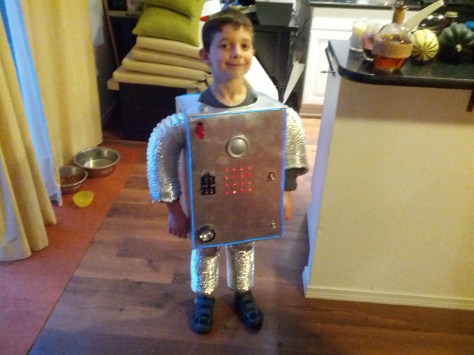
The bodies were constructed out of cardboard, spray-painted silver. The backs were open and got taped closed when the costumes were worn. The arms and legs were 4″ flexible dryer vent hose, and the legs were taped to a pair of shorts, which were covered in foil tape. Aesthetically, they came out just as I had envisioned, looking every bit the old fashioned sci-fi robot. Functionally, this design was flawed: my younger son didn’t have enough freedom with his legs to climb steps, which was a problem when trick-or-treating in our neighborhood. If I had it to do over again, I would have cut the boxes off at the waist. I also would have done something to decorate the neck hole, and maybe provided some headgear.
I had already settled on the Arduino Uno as the platform for this project (mostly because I already had some), and those totally suck at making noise. In the end, I did two things: first, I bought a couple of cheap voice changer toys, which I ripped apart and bolted into my robots (for cardboard and plastic values of “bolted”). The guts of the toy were taped up inside the body, the microphone was mounted on top, and the speaker was mounted in front. Hot glue secured the external components, and the red covered switch in the upper corner controled the toy’s battery. The toy supports several voice changing modes, but I didn’t expose that switch. I left it set to “robot”. I also used the High-Low Tech Group’s PCM audio library to produce sound from the Arduino. I found a nice “robot walking” sample online.
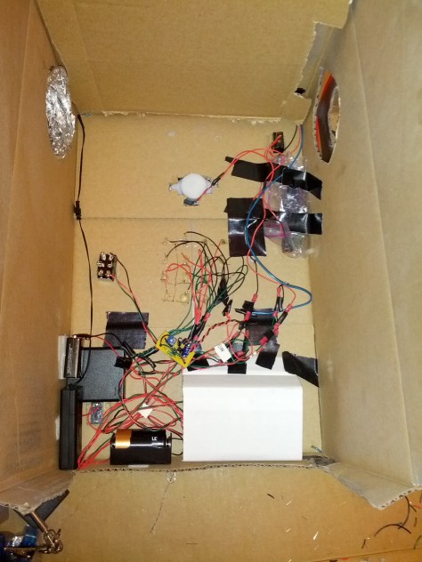
I built proto shields to hold all of the non-Arduino components I needed for the LED grid and the robot walking sound. These included resistors to limit current though the LEDs, the accelerometer for detecting walking, and leads to connect to the speaker, the LEDs, and the relevant switches. These worked out great, but I should have socketed the accelerometer boards, since I knew I’d want to reuse them for other projects.
The 4 x 4 grid of red LEDs below the speaker are poked through the cardboard and hot glued from behind. They have two modes of operation: random flashing or always on. The switch on the left side (wearer’s left) controls the LEDs. It’s a 3-position switch: center-off, up all-on, down flashing. The LEDs are wired in 3 groups (randomly selected as I was soldering them), and each of these groups is wired through a 100 ohm resistor to a pin on the arduino. The groups are randomly switched on and off (in the “flashing” mode), which produces an effect that looks just right to me.
The big knife switch on the right (wearer’s right) controls the walking sound. This is my favorite feature of the costume. I used an MMA7361 accelerometer board in high sensitivity mode to detect motion, simply by summing up all of the movement on all 3 axes and deciding that walking was occuring if those all added up to more than an empirically determined threshold. When motion was detected, the Arduino would use the PCM audio library to play the robot walking sound through the speaker.
Once I had it all built, it became clear that the walking noise was not loud enough, especially if both the voice changer and the walking sound were active at the same time (they shared the speaker). I built a little LM386-based audio amplifier to beef up the walking noise, which made a big difference.
The walking light is built from the head of an LED flashlight, controlled by the switch near the bottom. It angles slightly down, and is secured with hot glue. This is the “useful” feature.
The front and top of the costume are edged in el wire (red for one build, blue for the other). This looked really great when we were out trick-or-treating in the dark! This is the only feature that is not switched externally. I used the el wire controller to switch these on as the child was loaded into the costume.
In all, this costume had 5 different power systems. A bank of 4 AAs powered the Arduino, which powered the LEDs and provided the input for the audio amplifier. The amp used a 9v battery. The walking light used a single D cell. The voice changer toy had its own (tiny!) 12v battery, and the el wire came with its own battery-powered driver (2 AAs). If these costumes were going to get enough use to ever need to change any of the batteries, I would have looked at driving most or all of it from a single power source. Since they were only ever going to be worn to one Halloween party and one night of trick-or-treating, I didn’t bother.
The costumes did pretty well in the field. My older son (6, at the time) had no trouble getting around or using his arms, though he did have a little trouble squeezing himself into the thing. My younger son (3-almost-4, at the time) had no trouble getting in, but the body of the costume came down so low, he couldn’t raise his knees to climb steps. And the body was so wide, he could not touch his hands in front of himself, had trouble feeding himself, and could not reach to push himself up when he fell. Which he did. A lot. By the end of the night, one voice changer had stopped working, and one group of LEDs had gone out (and then later come back on). Considering the abuse that a 6 year old and a not-quite-4 year old can deliver, I was very pleased with these results.
Halloween has long been a favorite holiday, and I love the opportunity it provides for implementing fun and otherwise useless physical projects. This year, since my kids were both wearing store-bought costumes (and refused my offer for hand-crafted wooden swords, much to my surprise), I thought I’d do a little work on the decorations. My wife picked up a full sized skeleton to sit on our front porch, so I decided to give it some spooky red eyes and to breathe a little life into it by rocking its chair.
There are many examples on the web (Makezine’s, for example) of doing this kind of project with a windshield wiper motor. They’re strong, they run on 12v, and they run at around the right pace. I didn’t have a windshield wiper motor, but I DID have some crappy DC motors that I’d salvaged from a dead “Black Friday” printer, so I gave it a go with one of those.
To secure the motor, I clamped it to a wooden board, then zip tied the board to a fold-up sawhorse. To interface with the motor, I used InstaMorph. InstaMorph is a polyester thermoplastic that melts nicely in the boiler water from my espresso machine. I used this to form a spindle with a flange at one end, then I jammed the shaft of the printer motor (which had a small gear attached) into the other end. I pressed the plastic down around the gear as it cooled, and the result was a spindle that was firmly attached to the motor. I drilled a hole through the middle, tied some nylon twine through the hole, and I was ready to rock my chair.
It turns out that we had a small skeleton from Halloweens past, and my son had the wonderfully creepy idea to have the larger one cradling the smaller one as they rock. Using some small panel-mount LEDs and many feet of 22ga hookup wire, I gave them both glowing red eyes. The bundles of wire exiting the bases of their skulls gives the skeletons a lovely H. R. Giger vibe.
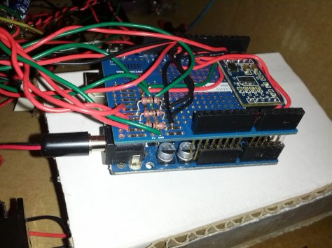
The heart of the project is an Arduino Uno. I can’t say enough wonderful things about this little workhorse. It’s not the fastest thing you can get at its size, nor is it the most capable, but they’re cheap, they’re robust, and the community support for them is outstanding. In early incarnations of this project, I combined my Uno with an Adafruit Motorshield. This made driving the motor in two directions trivial, but it turned out to be consuming too many of the digital pins. Since I wound up with a rocking methodology that did not require me to spin the motor in two directions, I swapped out the motorshield for an N-channel MOSFET. The transistor, the rest of the hardware to support the motor, an on/off switch, and an extra header full of ground connections all got soldered onto a protoshield. The eyes insert into 4 of the digital pins and 4 of the ground connections on the extra header, and another digital pin (as well as the +5v and one more ground header) went to a Parallax Ping.
I threw a header onto a fragment of a prototyping board, just to have somewhere portable to plug the sensor into. I wired about 10′ of cat5 (just 3 conductors) to that board, and I also soldered some short lengths of 22ga wire to the other end of the cat5. My cat5 is much thinner than 22ga and inserts poorly into breadboards and headers.
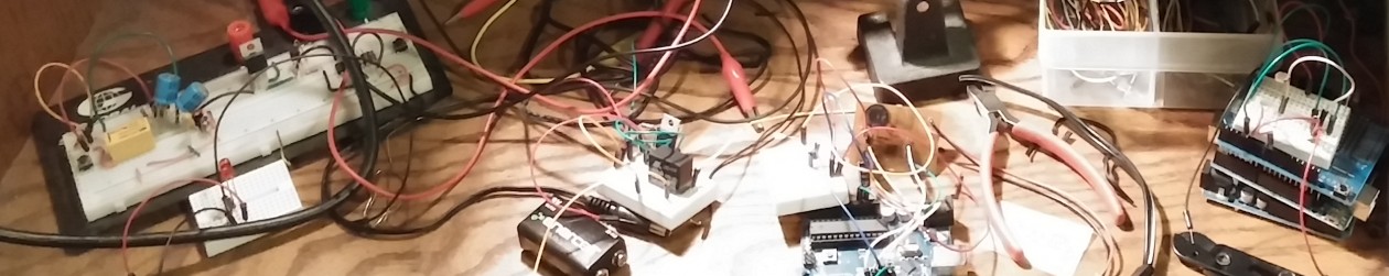
Here’s a quick walkthrough of the whole system, laid out in my dining room on the day before Halloween:
Installation was straightforward. I positioned the sawhorse behind the rocking chair, looped the twine over one of its slats, and programmed the motor for half a second on, three seconds off. This produced a noisy, spastic rocking that was in no way awesome, but was entirely good enough. The eyes, on the other hand, WERE pretty awesome.
This was a really fun project, and I was able to put it together using only components that I already had laying around my workshop. I was really pleased that I was able to produce an acceptable rocking motion using only a dc “hobby” motor, and the InstaMorph worked wonderfully for physically interfacing with the motor. And it looked super creepy in the dark.